
Thomas Tilley
[ Home ] [ Publications ] [ Resume ] [ Family ] [ Projects ] [ The Others ] [ Sitemap ]
[ Home ] [ Publications ] [ Resume ] [ Family ] [ Projects ] [ The Others ] [ Sitemap ]
 | |
 | |
 | |
 | |
 | |
 | |
 |

This is my prize winning entry for
the African
Robotics Network
(AFRON) $10
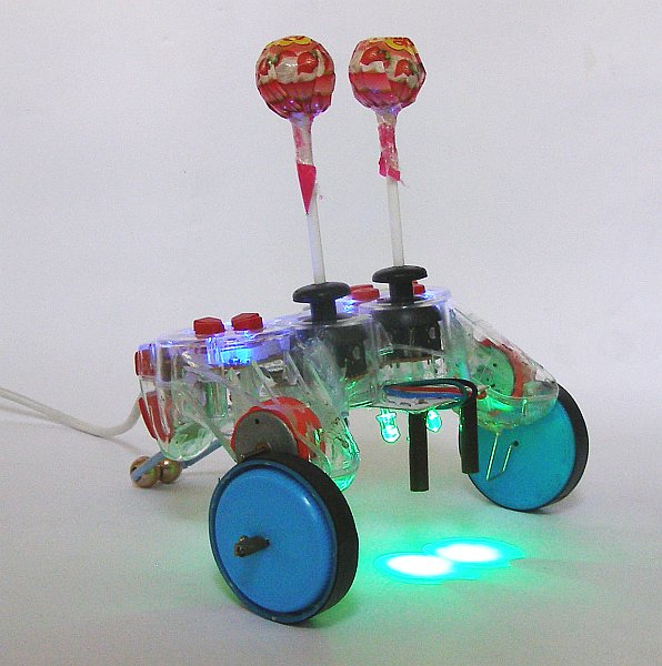
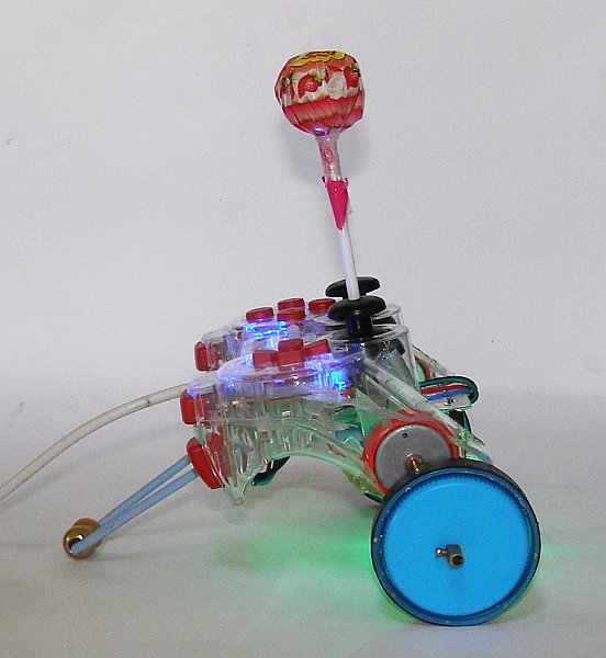
Robot Design Challenge: Lollybot (formerly known as "Suckerbot"). Suckerbot was a submission in the tethered robot category. The robot is connected to a computer via a USB cable where both the computing and the programming take place. You will find the contents of my submission below:
Contents
1. High-level Design
2. Educational Applications
3. List of Parts
4. Other Tools and Equipment Needed
5. Drawings
6. Step-by-step Instructions
7. Mass Manufacturing Cost (Not Applicable)
8. Software
9. Experiments
10. Pictures
11. Videos
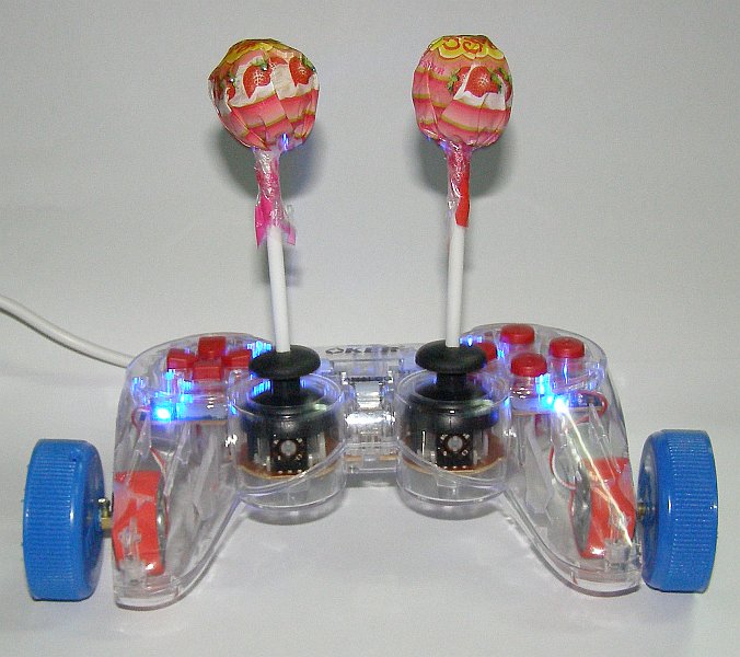
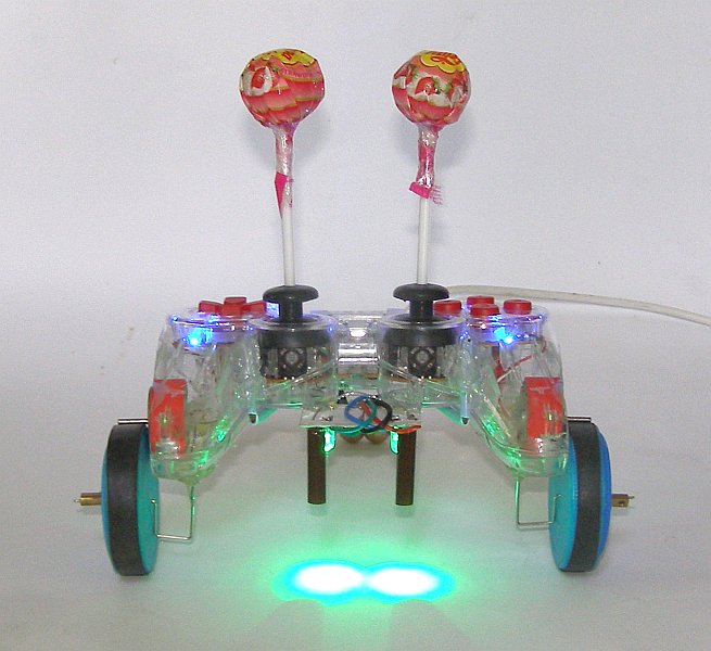
Lollybot is essentially a modified Dualshock-like USB joystick with wheels, a Chupa-Chupa bump sensor on one thumbstick, and a line sensor patched in to the other thumbstick. The robot is designed to be built from scratch by the user for a total cost of US$8.96 (excluding scavenged parts).
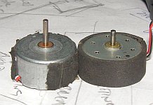
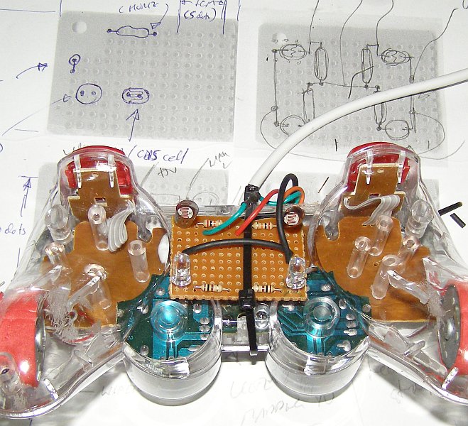
I have been using hacked joysticks to connect things to computers or game consoles since 2005 including: a wooden Dance Dance Revolution (DDR) mat, bamboo and PVC racing cars, motorbikes, virtual pinball machines, a voting machine, and custom Guitar Hero controllers. The joysticks provide a cheap, plug-and-play USB interface with 17 on/off digital inputs (16 buttons plus the "analog" button), 4 analog inputs (two thumbsticks each with X & Y axes), and two rumble motor outputs (see the images below).


In a 2009 paper for the Computer Games, Multimedia & Allied Technology conference I proposed building a robot from a USB joystick and I already had code that I'd developed for some earlier projects (written in Object Pascal to read joystick buttons and control rumble motors) but the AFRON $10 Robot Design Challenge gave me the motivation to finally try and implement something.
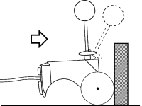 My
original vision was to mount a pair of wheels on the rumble motors
which could pull the joystick along the ground. I though that by
vertically extending the analog thumbsticks with two pens or
chopsticks it would turn them into simple bump sensors or primitive
accelerometers that would deflect when the robot ran into something -
possibly giving a crude measure of both force and direction. The robot
could drag itself along the ground until it bumped into something,
then it could reverse, turn, and drive off again until it ran into
something else. With some code to control the robot this would meet
the minimum requirements in the "tethered" category of the design
challenge and for less than $10.
My
original vision was to mount a pair of wheels on the rumble motors
which could pull the joystick along the ground. I though that by
vertically extending the analog thumbsticks with two pens or
chopsticks it would turn them into simple bump sensors or primitive
accelerometers that would deflect when the robot ran into something -
possibly giving a crude measure of both force and direction. The robot
could drag itself along the ground until it bumped into something,
then it could reverse, turn, and drive off again until it ran into
something else. With some code to control the robot this would meet
the minimum requirements in the "tethered" category of the design
challenge and for less than $10.
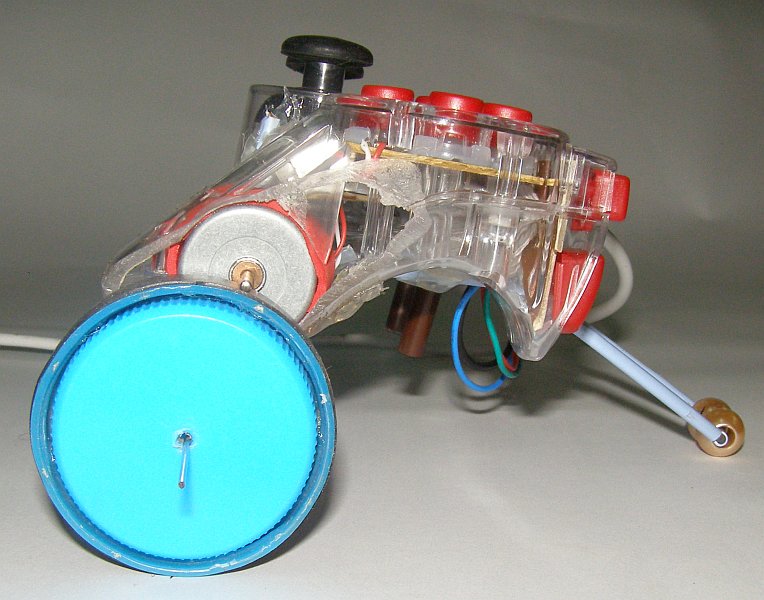
As I thought more about this design I realised that a mass on the end of a shaft - weighing just enough that the thumbstick springs were still able to return to their center position - would make a better "bump sensor". I have always been a fan of Chupa Chups (a friend even paid me in Chupa Chups for a job I did once!) and I realised that the classic 11gm Chupa Chups (especially Strawberry and Cream flavoured ones) should work. Mounted on top of the thumb sticks they looked appealingly like eyes or antennae. Apparently the name "Chupa Chups" comes from the verb for "suck" in Spanish so I originally decided to call my robot "Suckerbot".
Unfortunately, as I thought further about the design I realised that for the robot to be able to reverse after hitting something it would need to be able to swap the motor polarity or use some sort of reverse-gear mechanism. Although I could think of some possible ways to do this (e.g. a bump switch and circuit that would temporarily reverse the motor wiring) it meant extra cost and complexity. Alternatively, if the wheels were mounted in an appropriate position and if they were strong enough, it may still be possible for the robot to be able to turn so that it could continue in another direction.
As I experimented with different wheel designs (you can see the progression of Lollybot's wheel design in the Experiments section below) I discovered very quickly that the motors were not powerful enough to drive wheels mounted directly on their shafts and that I would need to increase the torque using a gearing mechanism. This would reduce the speed of the robot and as a result the "bump sensors" would no longer work. I liked the look of the Chupa Chups so I decided to keep them as part of the design anyway but they could easily be replaced by wire "feelers" that bent over in front of the robot to detect objects in the robot's path.
While the bump sensors didn't work as I originally envisioned, they could still be used to interact with the environment (see the "robot arena" idea in the Education section below) but I decided to add at least one other type of sensor for the design challenge. Line following is a classic educational robot feature and I decided to build a very simple circuit with two line sensors where each of the sensors would be patched into an analog joystick axis.
The resistors inside the analog thumbsticks are set-up as voltage dividers that vary the voltage going to the axis sensor between 0 and 5 volts depending upon the position of the stick. The joystick hardware then converts this analog voltage into a digital value between 0 and 255 (where the center or middle position for the stick is 127).
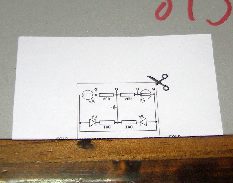
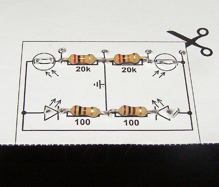
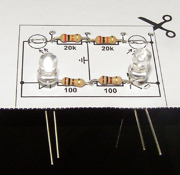
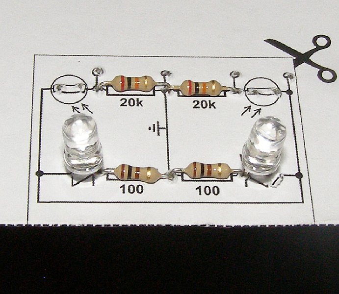
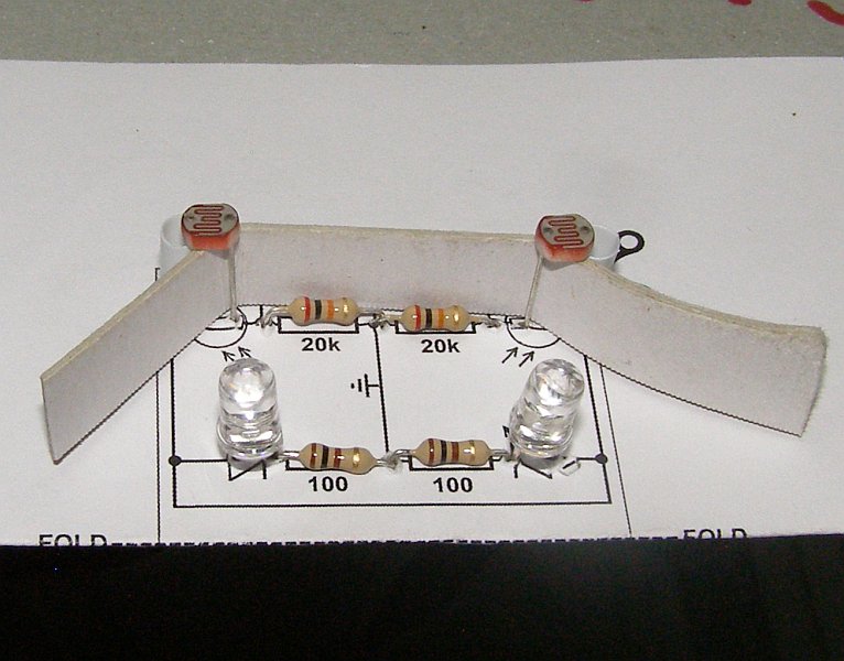
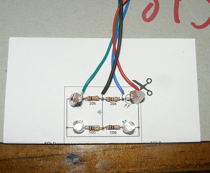
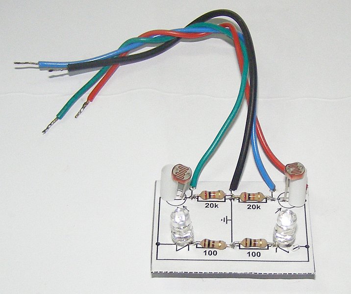
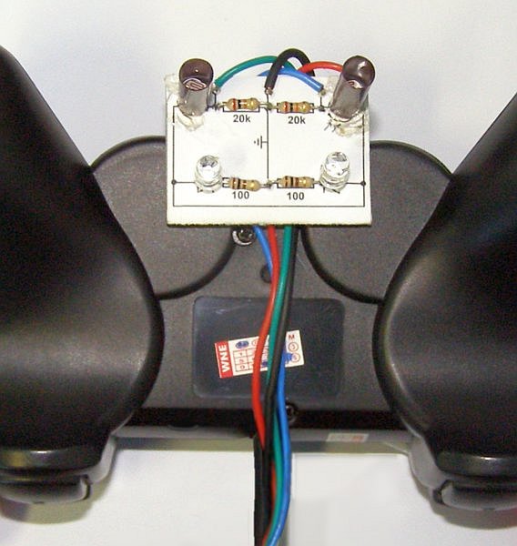
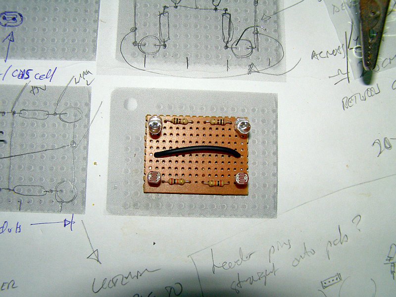
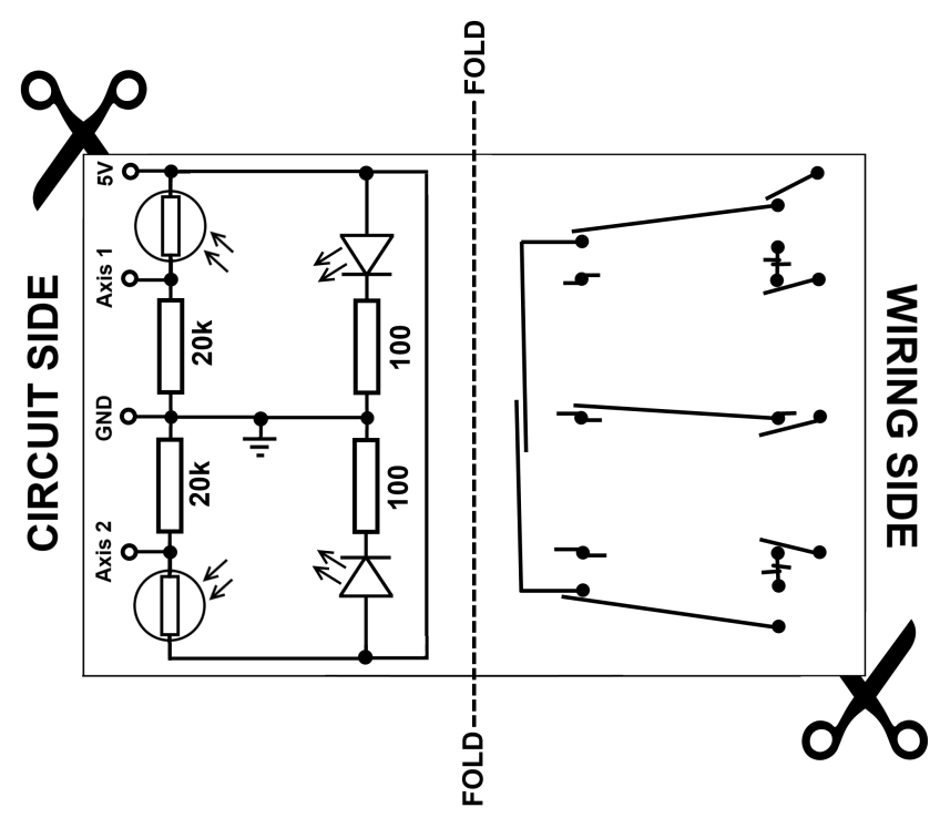
 My circuit for a single line
detector/sensor is shown left with
a Light
Dependent Resistor (LDR) and a 20kΩ resistor set-up as a
voltage divider. The right hand-side of the circuit is
a Light
Emitting Diode (LED) with a
100Ω current
limiting resistor. The LDR is mounted in a small tube that
shields it so light from the LED doesn't reach it directly but is
reflected off the floor beneath the robot instead. The resistance of
the LDR varies depending upon the amount of light it receives with the
resistance decreasing as the amount of light increases. If we replace
the original joystick resistor with this circuit then the robot's
software can read the joystick axis values and determine if the sensor
is positioned over a dark line or a lighter-coloured background. In
the Parts section below I have included
a printable template that can
be used to build a version of this circuit with two detectors that can
be mounted underneath Lollybot.
My circuit for a single line
detector/sensor is shown left with
a Light
Dependent Resistor (LDR) and a 20kΩ resistor set-up as a
voltage divider. The right hand-side of the circuit is
a Light
Emitting Diode (LED) with a
100Ω current
limiting resistor. The LDR is mounted in a small tube that
shields it so light from the LED doesn't reach it directly but is
reflected off the floor beneath the robot instead. The resistance of
the LDR varies depending upon the amount of light it receives with the
resistance decreasing as the amount of light increases. If we replace
the original joystick resistor with this circuit then the robot's
software can read the joystick axis values and determine if the sensor
is positioned over a dark line or a lighter-coloured background. In
the Parts section below I have included
a printable template that can
be used to build a version of this circuit with two detectors that can
be mounted underneath Lollybot.
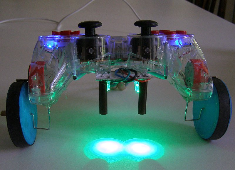
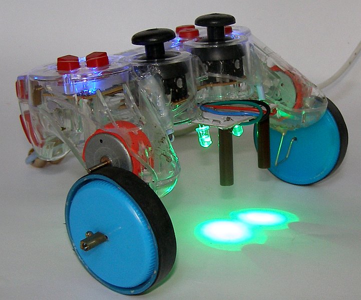
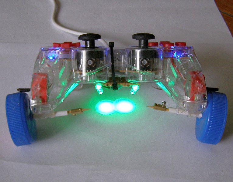
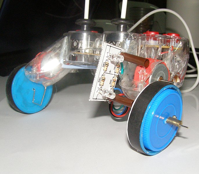
For less than $10 Lollybot provides students with a two-wheeled,
programmable robot that includes a bump sensor, line following
sensors, and delicious (preferably Strawberry & Cream flavoured)
Chupa Chups! It is constructed from readily available parts using
common tools and it is simple enough for students to build themselves
either individually or in teams/groups. If you build a Lollybot, make
some improvements to the design, or if you have any questions or
suggestions then please email me
at lollybot@tomtilley.net.
What science and technology concepts or skills can Lollybot help students learn?
Students could also modify Lollybot's design to:
All of the parts required to build Lollybot were readily available here in Thailand and apart from paperclips they could be bought in single item quantities. For most of the parts where the representative online price is for multiple items (e.g. one pack of 4 glue sticks costs $1.99) I have divided the price by the buy quantity to give a per robot cost (one stick at $0.50). For more information see the "notes" column for each of the parts below.
| Part | Qty | Source | Price (US$) | Notes |
|---|---|---|---|---|
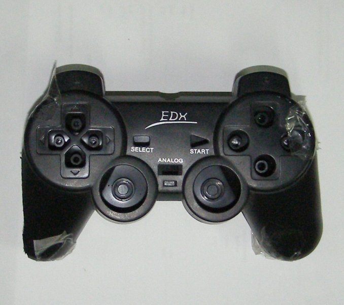
Dualshock-like USB Joystick  |
1 | Available here in Thailand for 100THB ($3.23 USD). e.g. Joyeb | $3.80 | €2.94 is approx. US$3.80. See the note below about buying joysticks. |
Chupa Chups (11gm)  |
2 | e.g. Candy Warehouse | $0.50 | You can buy 100 lollipops for $25.00 online ($0.25 per lollipop). Any flavour will work but Strawberry and Cream is my favourite! |
100Ω, 1/4 watt resistor  |
2 | e.g. Allied Electronics | $0.03 | Must buy a minimum of 10 online ($0.15 total). 10 resistors are enough for 5 robots. |
20KΩ, 1/4 watt resistor |
2 | e.g. Allied Electronics | $0.03 | Must buy a minimum of 10 online ($0.15 total). 10 resistors are enough for 5 robots. |
Green LED, 5mm, 20mA  |
2 | e.g. Allied Electronics | $0.84 | |
Light Dependent Resistor (LDR) ") |
2 | e.g. Allied Electronics | $1.32 | |
Line Sensor Circuit Template  |
1 | Right here! | $0.00 | Print either this PDF version or this PNG version actual size. |
Sheet of A4 copier, 80gsm  |
1 | e.g. Office Depot | $0.02 | A ream of 500 sheets costs $9.29 ($0.02 per sheet). Print the template on this piece of paper. One sheet is enough for 4 robots. |
Cardboard, approx. 10cm x 10cm  |
1 | Scavenged! | $0.00 | |
Glue Stick or Paste  |
1 | e.g. Office Depot | $0.50 | A pack of 4 glue sticks costs $1.99 ($0.50 per stick). One stick should be enough for at least 20 robots! |
Small Juice-box Straw  |
1 | Scavenged! | $0.00 | This will be used to insulate the LDR leads. Alternatively you could use a Chupa Chup stick, empty plastic ballpoint pen ink tube, or make a small paper tube instead. |
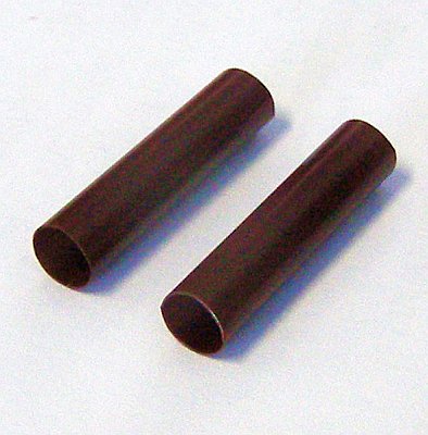
Plastic Drinking Straw (Brown or Black)  |
1 | Scavenged! | $0.00 | Shields for the Light Dependent Resistors. One straw is enough for 4 robots. You could make your own paper tubes instead. |
Coloured Hook-up wire  |
48cm | e.g. Ham Radio Express | $0.95 | Ideally 4 x 12cm lengths in 4 different colours. The linked source is for 16' of wire (approx. 487cm) which is enough for 10 robots. |
Container lids for wheels  |
2 | Scavenged! | $0.00 | At least 45mm in diameter |
Container lids for the wheel hubs  |
2 | Scavenged! | $0.00 | These must fit inside of the larger container lids used for the wheels (see above) |
Old bicycle tire inner tube  |
1 | Scavenged! | $0.00 | One 22" tube is enough for more than 80 robots. |
Paper clips (large)  |
2 | e.g. Office Depot | $0.02 | A box of 100 clips costs $0.99 ($0.01 per paperclip). |
Screw terminal block  |
1 | e.g. Allied Electronics | $0.39 | |
Wire Coathanger  |
1 | e.g. Amazon | $0.17 | For the tail skid. 40cm of similar gauge wire would be OK. 100 hangers costs $16.95 ($0.17 per hanger) |
Plastic/ceramic beads  |
2 | e.g. Consumer Crafts | $0.01 | Rollers on the tail skid. The hole diameter should be large enough to fit the coathanger wire. One pack of 360 beads costs $1.97 (less than $0.01 per bead). One pack is enough for 180 robots! |
Hot-melt glue stick  |
1 | e.g. Save-on-crafts | $0.38 | A pack of 8 sticks costs $2.99 ($0.38 per stick). One stick is enough for 2 robots. You could use two-part epoxy resin instead of hot-melt glue. |
| TOTAL | $8.96 | |||
A note about buying joysticks: - Any Dualshock-like joystick with a model no. ending in "706" or "401" should be suitable for making a Lollybot - even those with a slightly different body shape should work (although you will need to adapt the instructions from Section 6 below). However, there are two things to watch out for when buying joysticks:
All of the required tools and equipment are reasonably common and should be safe for students to use with appropriate supervision (especially for the craft knife, electric drill, soldering iron, and hacksaw).
| Tool/Equipment | Estimated Price (US$) |
Notes |
|---|---|---|
Small Flat Blade Screwdriver  |
$3.00 | Used for tightening/loosening the terminal block screws. |
Small Phillips-head Screwdriver  |
$3.00 | Used to remove/tighten the screws holding the joystick together. |
Hacksaw  |
$15.00 | |
Pliers  |
$5.00 | For cutting and bending coathanger wire. |
Side Cutters  |
$5.00 | For clipping the leads on electronic components. |
Long-nose Pliers  |
$5.00 | For bending/assembling electronic components and removing the motor weights. |
Twist Drill Bit (3.5mm/0.1378" diameter)  |
$3.00 | The shaft should be the same diameter as a Chupa Chupa stick - approx. 3.5mm |
Hand Drill or Power Drill  |
$30.00 | This may be optional. It is used for drilling holes in the joystick's thumbsticks to hold the Chupa Chups. You could melt a pilot hole in the thumbsticks and then manually turn the drill bit to make the hole but it is easier with a hand or power drill. |
Soldering Iron & Solder  |
$20.00 | 25-40 Watt iron for working with electronics |
Craft/Utility Knife or Pocket Knife  |
$2.00 | |
Scissors  |
$2.00 | |
Hot-melt Glue Gun  |
$10.00 | This may be optional. You could use two-part epoxy resin instead of hot-melt glue. |
PVC Pipe (18mm diameter, approx. 20cm long)  |
$1.00 | A piece of broomhandle, dowel or bamboo may suffice but the diameter needs to be slightly less than the diameter of the joystick's rumble motors. |
Coarse Sandpaper (1 sheet)  |
$1.00 | |
Rubber Bands (2 or 3)  |
$0.05 | |
Sticky Tape  |
$2.00 | Alternatively you can use electrical tape, packing tape, or duct tape. Approx. 25cm of tape is all that is needed. |
Drawing Pin, Thumbtack, Push Pin, or Sharp Nail  |
$0.05 | |
Black & White Inkjet or Laser Printer  |
$50.00 | Used for printing the circuit template. |
Analog or Digital Multimeter  |
$15.00 | This is optional. It is useful for checking the line following circuit and the joystick traces but if you work carefully it is not essential. |
Digital Camera or Phone with a Camera  |
$80.00 | This is optional. It is useful for taking photographs of the joystick as you pull it apart so that you can reassemble it correctly. |
Click on the images below to see the larger drawings with dimensions. Apart from any angles, all units are in millimetres (mm) and although the measurements are correct the scale on the drawings is not accurate.
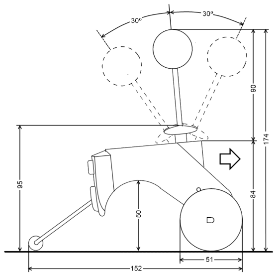 Side View |
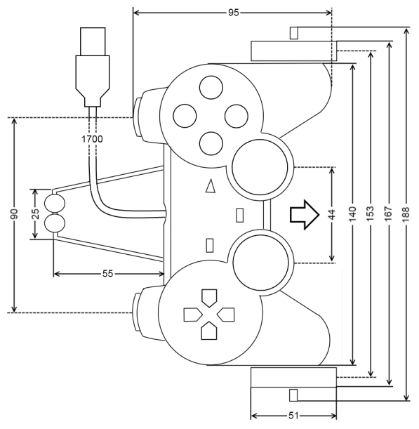 Top View |
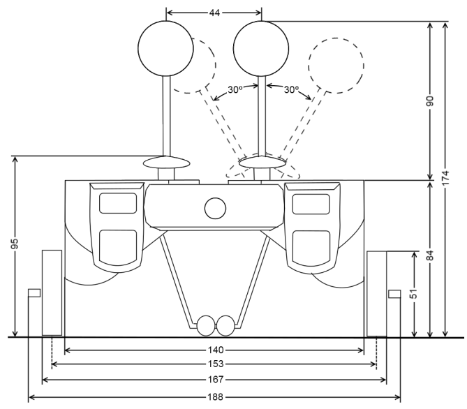 Rear View |
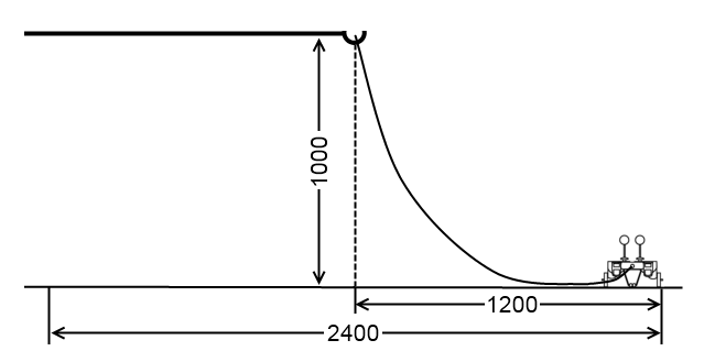
The joystick I used to make my robot comes with a 1.7m USB cable. I used a 5m USB extension cable to connect Lollybot to the computer and suspended the point where the cables connect about 1m above the floor (using some PVC pipe). This allows the robot to travel and turn within a circle about 2.4m in diameter.
Here are the instructions for making your own Lollybot. Follow the steps carefully and please read all of the instructions for a particular step before you start that step.
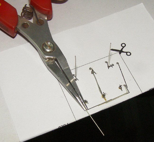
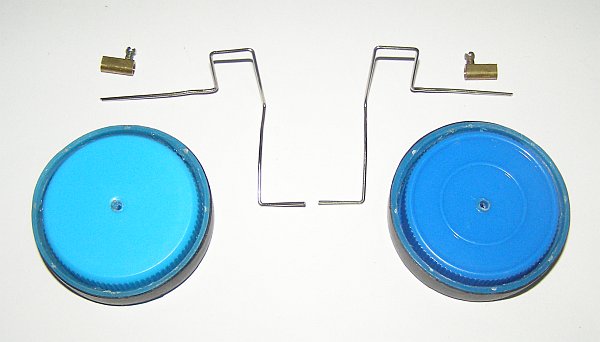
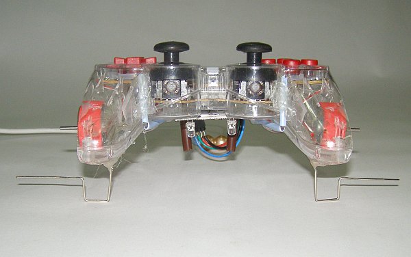
If you are working alone you can simply work through the 15 steps below in order. However, if you are working with others then three different people or groups can work in parallel to: modify the joystick (steps 1-5), build the line sensor (steps 6-12), and make the wheels (steps 13-15) (see the image below). The first two groups will need to work together in step 11 and this will need to be completed before the "wheel group" can finish step 14.

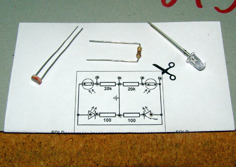
For this step you will need these parts & tools:
| Parts | Tools |
|---|---|
|
|
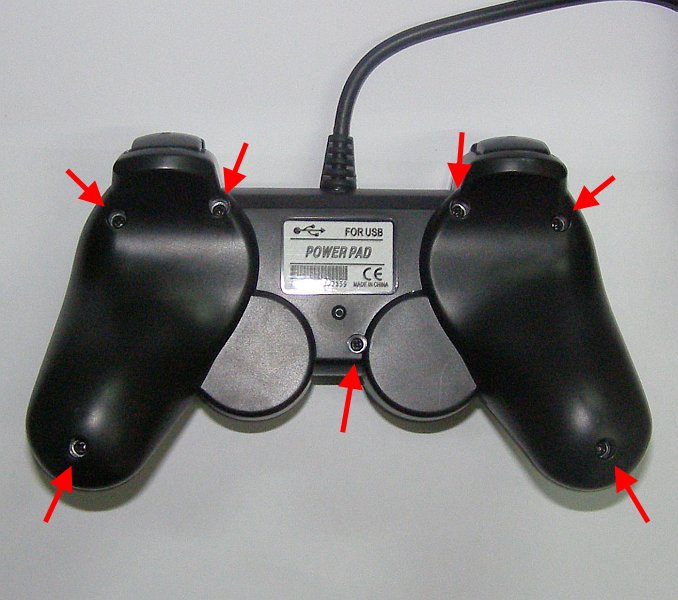
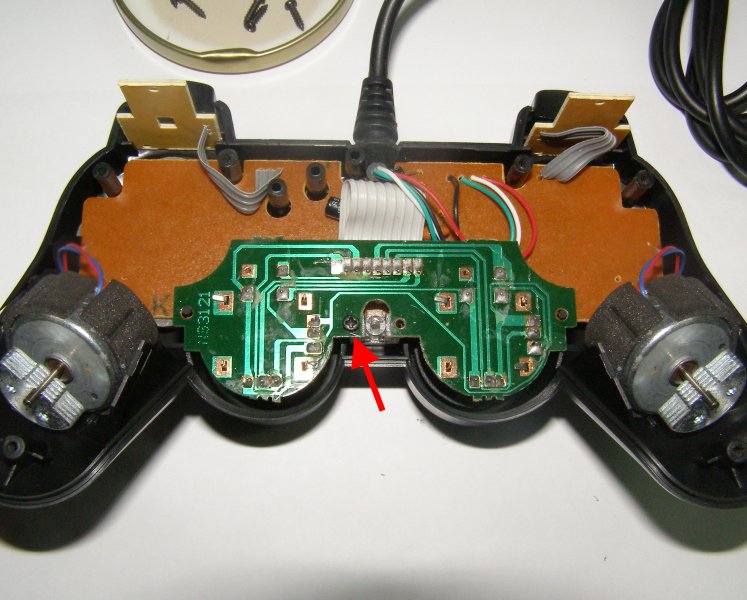
Lay the joystick upside down on a flat surface and remove the 6 or 7 screws (depending on the model) holding the joystick together (see the first image below) and put them somewhere safe - perhaps in a plastic jar or cup - so you don't lose them. Remove the back cover (the two larger finger buttons will come away with the cover - add them to your collection of small parts) and you should see something very similar to the middle image below with two rumble motors, a larger brown printed circuit board, a smaller green or blue board (for the thumbsticks) connected with grey ribbon cable, and two very small boards at the front of the joystick (for the buttons on the "front" of the joystick) also connected by grey ribbon cable. If you only find one motor then read the note on buying joysticks in the Parts section above.
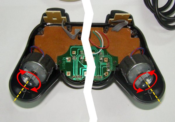
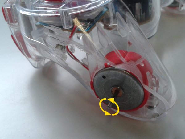
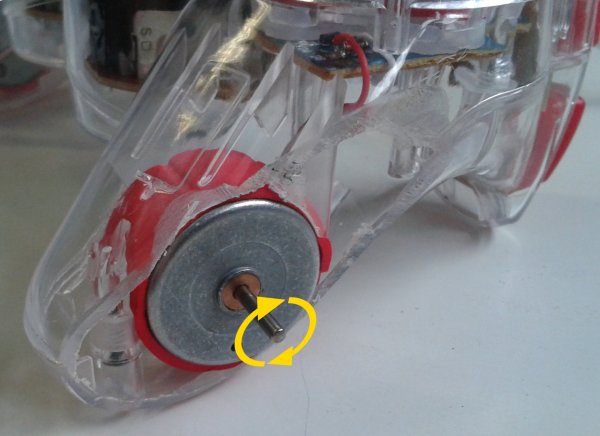
Before going any further you need to check which way the rumble motors rotate. The motors will be used to drive Lollybot's wheels and if they are going in the wrong direction your robot will try and go backwards or just turn in circles! Note that even two joysticks from the same manufacturer that look exactly the same can have motors that turn in different directions so you must check the joystick you are using! Later on in Step 12 you can change the direction of the motors if you need to.
You can make the motors rotate so you can check their directions using the "Game Controller" applet for your operating system or use the "Driving" mode in Lollybot's control software (which you will find in Section 8 below). If you imagine that your are holding the joystick normally then the right-motor (on the left in the picture below because the joystick is upside-down) should turn in a clock-wise direction while the left motor (on the right in the image below) should turn in an anti-clockwise direction. For now you just need to make a note of which way each motor turns.
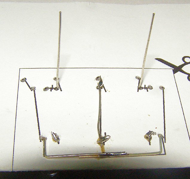
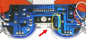
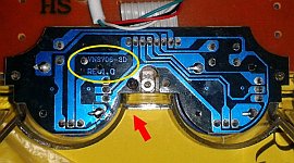
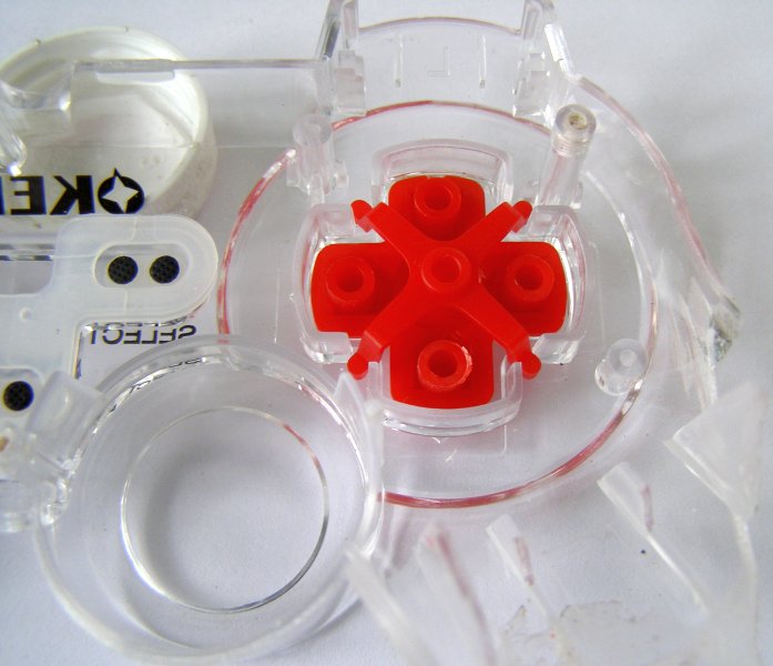
The green (or blue) thumbstick board is held in place with a single screw (follow the red arrow in the image below). Remove the screw and then carefully lift the thumbstick board up and fold it towards the front of the joystick (towards the USB cable). Beneath it you will see a small clear piece of plastic (in the red oval on the picture below right). This piece transmits light form the "analog" LED and also helps to hold the brown board in place. Make a note of how the part is positioned - you can take a picture of it if you have a digital camera or phone camera - and then remove it.
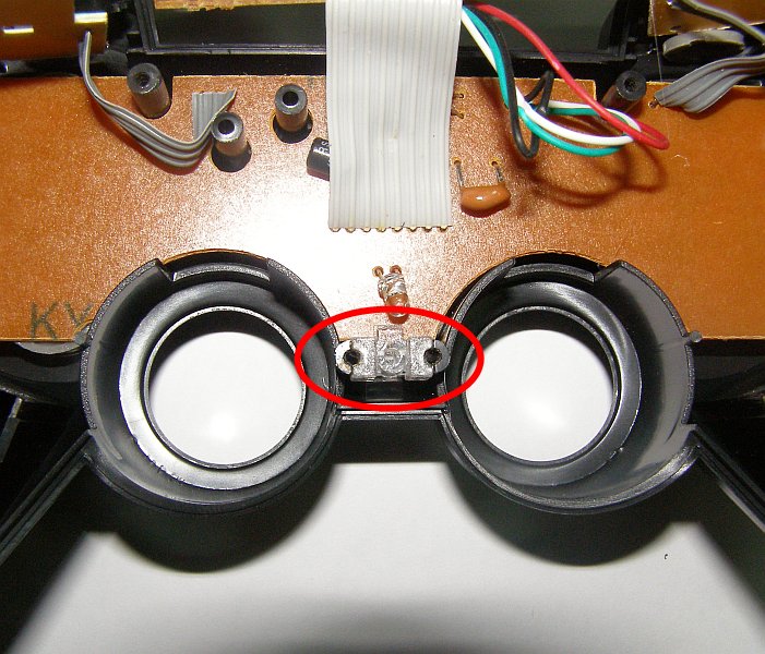
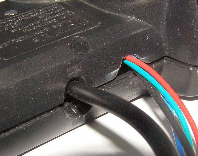
Before you remove the boards take a photo of the USB cable for future reference. You can now carefully remove the inside of the joysticks by sliding out the two small boards at the front, removing the rumble motors from their holders (note that some joysticks have a separate piece of plastic that holds the motors in place and you may need to remove the screws on these) and carefully lifting the brown and green (or blue) boards up and out.
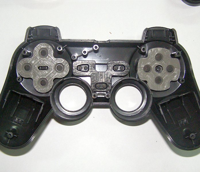
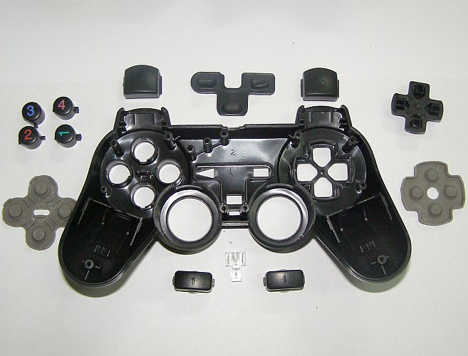
What remains should look like the image below left but sometimes the rubber buttons stick to the board - this isn't a problem - just pull them off carefully and put them safely with the other parts. Take some more photos as you remove all of the joystick's buttons so that you can put it all back together again later on.
Now put the two halves of the joystick back together again and secure the two halves with five pieces of tape as shown in the last picture below. Make sure you keep the boards and motors safe because you'll need them again soon.
For this step you will need these parts & tools:
| Parts | Tools |
|---|---|
|
|
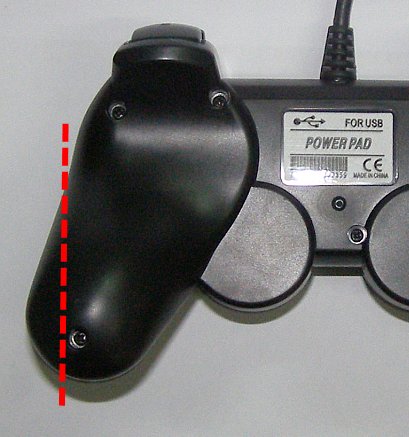
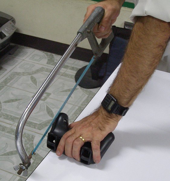
You are now going to cut the sides off of the joystick. If you look at the top of the joystick you will see that both the direction (or D-pad) buttons on the left and the "1".."4" button on the right are arranged inside of two large circles. You are going to cut from the side of the circle down through the hand-grip and just to the side of the screw hole in the hand-grip. See the first picture below.
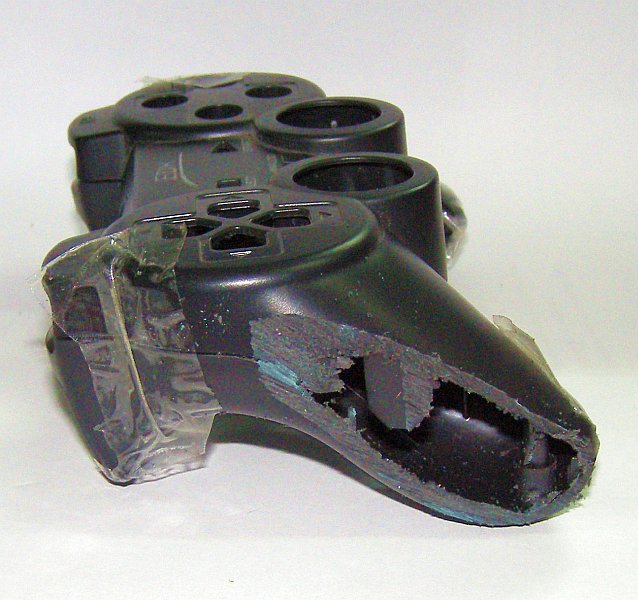
Hold the part of the joystick you are cutting over the side of table or bench and use the hacksaw to carefully cut through the side. Try and make a nice straight cut while keep the blade vertical and don' t damage the screw post inside (see the image below). When you are done it should look like the two images below right showing the side and top views. If you look carefully at the side view you can see the screw-post inside of the hole. Smooth off any rough edges with the sandpaper and then repeat for the other side. Don't cut yourself (or anyone else), or the table and make sure you clean up the table and floor afterwards!
For this step you will need these parts & tools:
| Parts | Tools |
|---|---|
|
|
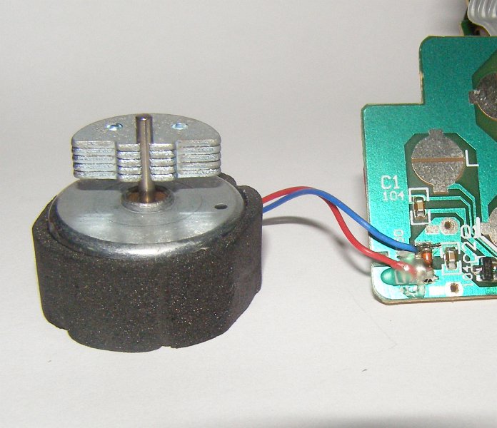
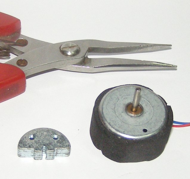
The rumble motors in the joystick provide haptic feedback by rotating offset weights that make the joystick shake. We are going to use these motors to drive Lollybot's wheels but first we need to desolder the motor leads from the brown circuit board (if you haven't used a soldering iron before this comic will help you) and remove the weights.
![]() Warning! Soldering irons are very
hot. Always be careful when using a soldering iron so that you don't
burn yourself (or others) and never leave an iron that is plugged in
unattended. The fumes from the solder flux or melted plastic can also
be toxic so don't breathe them in and work in a well ventilated area!
Warning! Soldering irons are very
hot. Always be careful when using a soldering iron so that you don't
burn yourself (or others) and never leave an iron that is plugged in
unattended. The fumes from the solder flux or melted plastic can also
be toxic so don't breathe them in and work in a well ventilated area!
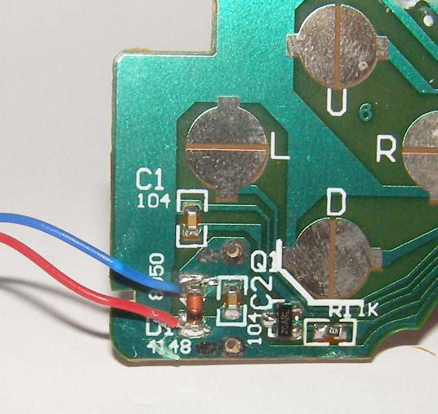
If you look at the left picture below you will see that there is some hot-melt glue covering the motor connections to the board. You should be able to peel this off carefully using your fingernails so it looks like the picture on the right. Make a note or take a picture of the motor connections on both ends of the board including the wire colours. Later on in Step 12 you will reconnect the motors and you can swap the wires over to change their direction if you need to. Now you can carefully de-solder the motor leads from the board.
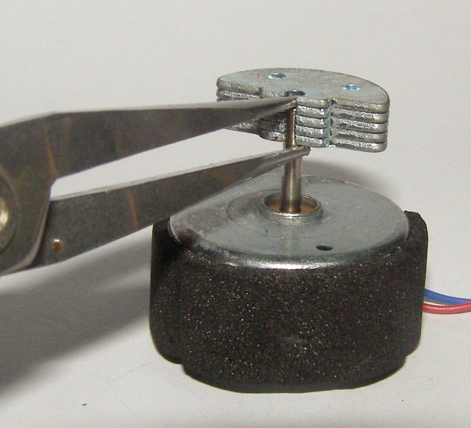
To remove the weights from the motor shafts you could try putting a screwdriver between the weight and the motor body and twisting it but I have damaged a motor this way so I suggest another technique. If you look at the rumble motor you will see that weight is mounted lower than the end of the shaft. We want to carefully slide the weight off of the shaft and you can start by using the long-nose pliers. Place one side of the pliers on the top of the shaft and the other side beneath the weight as shown in the picture below. Squeeze slowly and the weight should slide up slightly so the weight is now at the top of the shaft (see the picture below right).
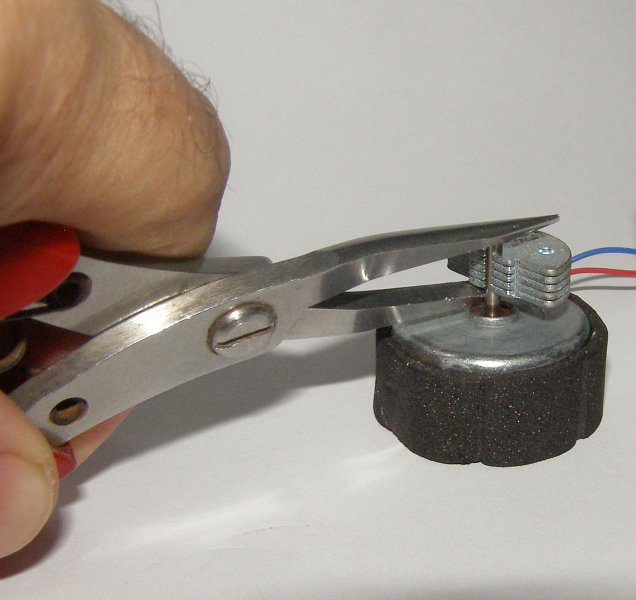
Now carefully place the very end of pliers on top of the shaft and try squeezing again. The weight should slide up the shaft over the end of the pliers. There are also some other alternative weight removing techniques you can try but be careful not to damage the motor! Repeat the process to remove the weight from the other motor.
For this step you will need these parts & tools:
| Parts | Tools |
|---|---|
|
|
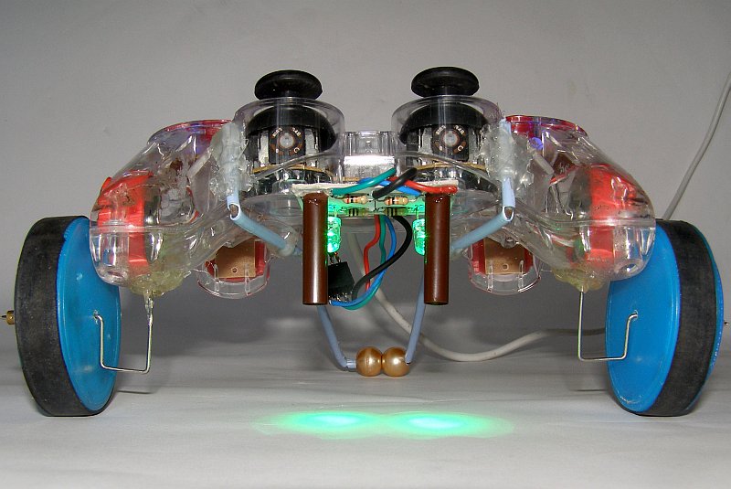
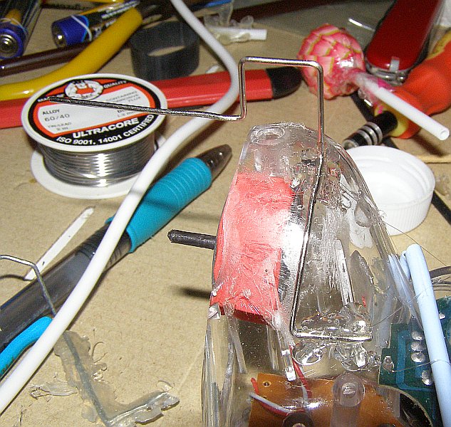
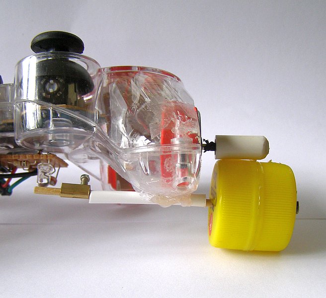
So the motors can drive the robot's wheels you need to carefully make a motor sized hole in the place where you cut off the sides of the joystick in Step 2. You should be able to slide one of your newly de-weighted motors in through the side of the hole so you can get an idea of how much plastic you will need to remove and where the motor will sit. See the picture below left.
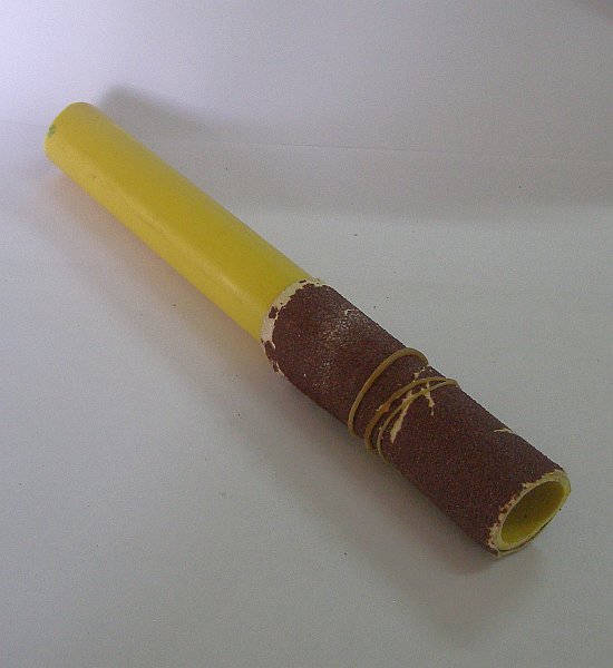
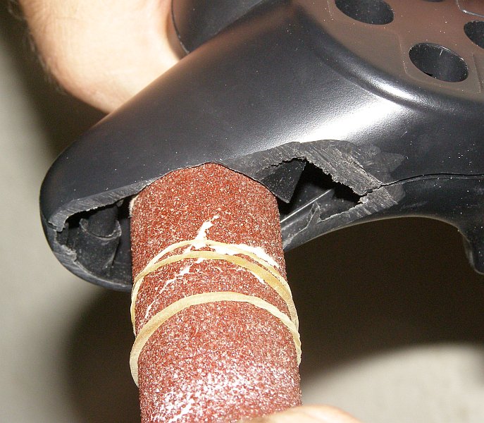
Take the PVC pipe (the diameter of the pipe should be slightly smaller than the diameter of your motors) and wrap the piece of sandpaper around the end and secure it with one or two rubber bands as in the picture below.
Now remove all of the tape except the piece along the edge where the USB cable normally goes. You should be able to open up the hand-grip end of he joystick and close it around the end of the sandpaper. By holding the sandpaper onto the PVC pipe and rotating it as well as sliding it in and out of the side you can enlarge the hole so that the motor just fits. It won't take as much work as you might think and you should stop often to check the size.
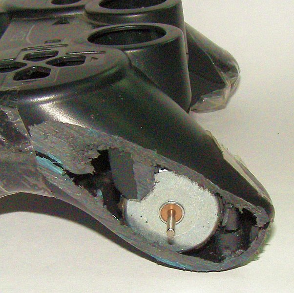
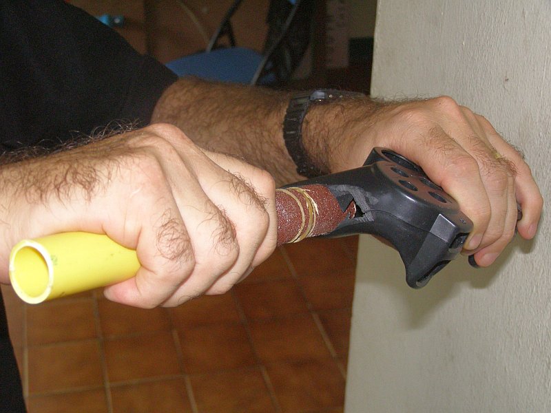
The hole should be positioned so the motor will sit up against the screw post and so that you can only just close the two halves of the joystick when the motor is in place. Don't remove any of the foam/rubber around the motor - this should be compressed tightly when the joystick halves are together. See the middle picture below
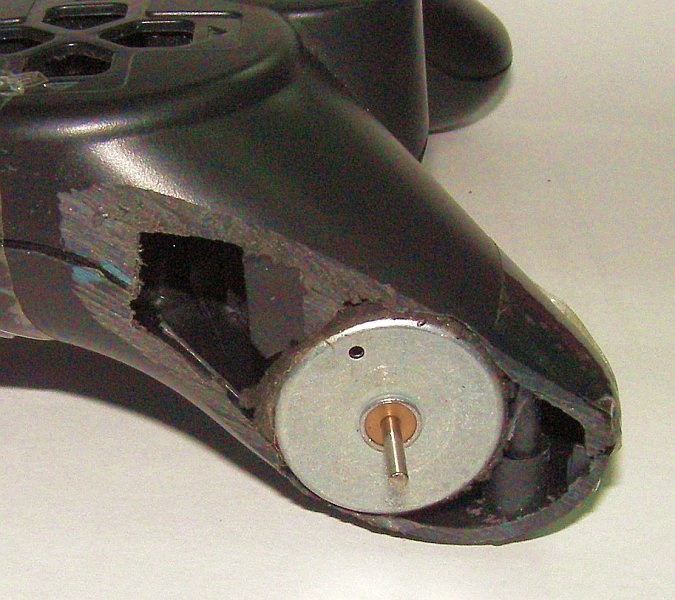
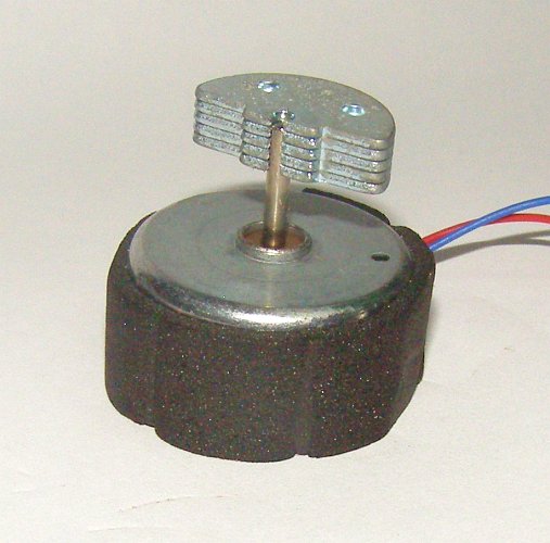
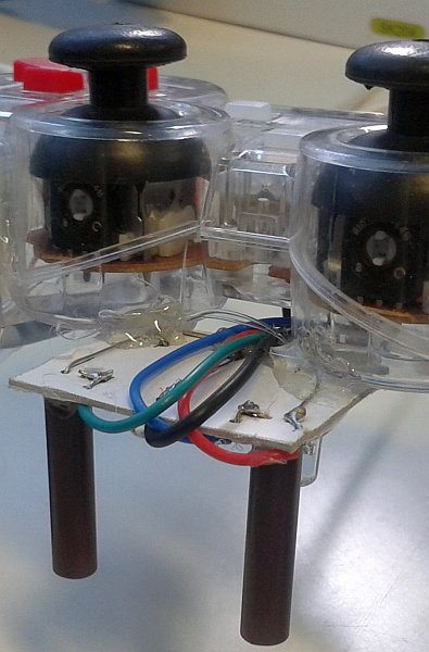
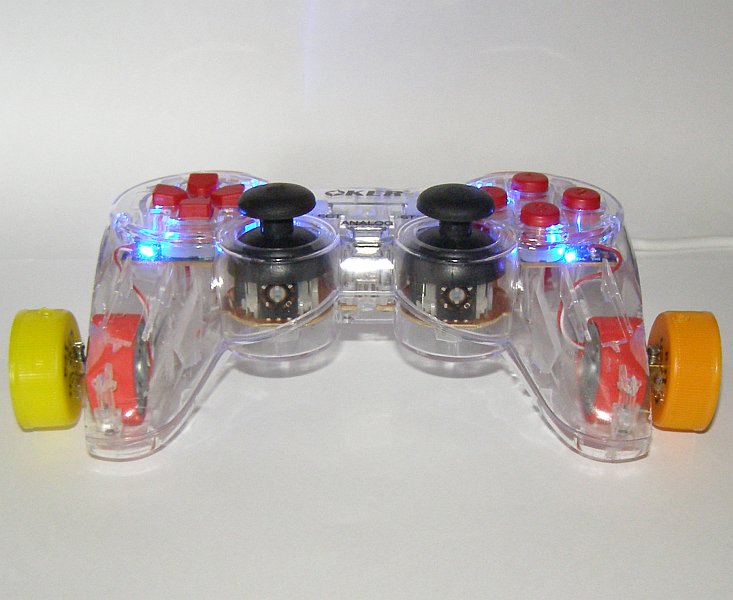
Try and keep the PVC pipe perpendicular to the side of the joystick
as you are making the hole. You will re-connect the motor wires and
fit them back inside the joystick shell in a later step but the final
result should look like the motor in the clear-bodied joystick above.
Repeat the process to make the hole on the other side of the joystick
as well.
For this step you will need these parts & tools:
| Parts | Tools |
|---|---|
|
|
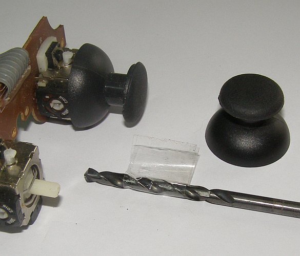
Lollybot's bump sensors are Chupa Chups mounted on top of the thumbsticks. If you pull up gently on the rubber thumbsticks they will slide off of the analog joystick mechanism. Next, check to make sure that your drill bit is the same diameter as the stick on the Chupa Chups (about 3.5mm) or slightly smaller.
You don't want to drill all the way through the thumbstick - only 1cm in from the top or you will damage the plastic section that holds the stick onto the actual mini-joystick. Measure 1cm in from the end of your drill bit and wrap a piece of tape around. This will act as a depth guide for you when you are drilling (see the middle image below).
Tape the thumbstick upright onto a suitable work surface and then carefully drill out the middle part while keeping the drill perpendicular to the top of the thumbstick. Use the tape guide on the drill bit to get the depth correct. The Chupa Chup sticks should fit tightly into the holes.

![]() Warning! Power tools are potentially dangerous. Make sure you follow any safety instructions that came with the drill and work on an appropriate surface.
Warning! Power tools are potentially dangerous. Make sure you follow any safety instructions that came with the drill and work on an appropriate surface.
| Parts | Tools |
|---|---|
|
|
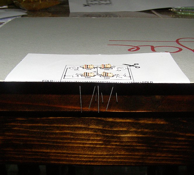
Print the line sensor circuit template on your piece of A4 paper but DO NOT CUT AROUND THE CIRCUIT YET! Fold the sheet of paper in half horizontally and half vertically to mark the paper and then cut it into quarters.
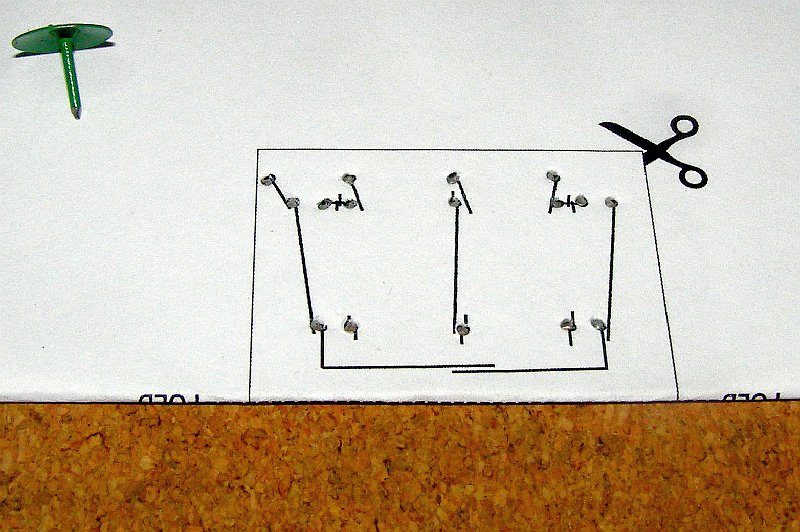
Next, fold the piece of paper with your circuit along the dotted line. Glue the piece of paper onto the cardboard so that the fold is along a straight edge (see the left diagram below). Make you sure you glue both sides and that the fold is right on the edge of the cardboard - this will help the two sides to line up correctly. On one side of the cardboard it should say "CIRCUIT SIDE" and the other side should read "WIRING SIDE".
The size of the piece of cardboard isn't very important but we will use it to hold the circuit while we are working on it. I used the cardboard from the back of an old notepad. Cardboard from a cereal box would be fine but the brown corrugated cardboard used for packing boxes is too thick. DO NOT CUT AROUND THE CIRCUIT YET!
Place your circuit with the "WIRING" side up and use the drawing pin to carefully make a hole where each of the 16 black dots appear (see the middle picture below). Turn the circuit board over to the "CIRCUIT" side and it should look like the picture on the right. Now we are ready to start adding the components.
![]() Warning! This
circuit doesn't generate much heat and is very safe but be very
careful if you are going to use this approach to build your own
circuits because it could be a potential fire hazard.
Warning! This
circuit doesn't generate much heat and is very safe but be very
careful if you are going to use this approach to build your own
circuits because it could be a potential fire hazard.
| Parts | Tools |
|---|---|
|
|
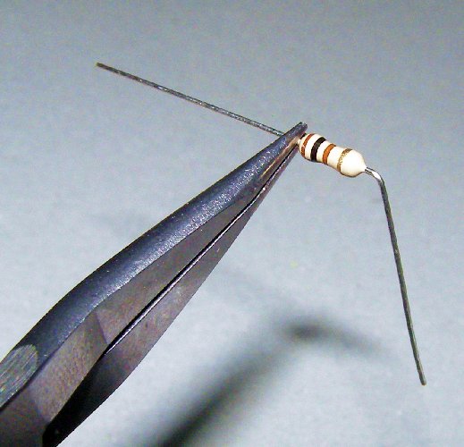
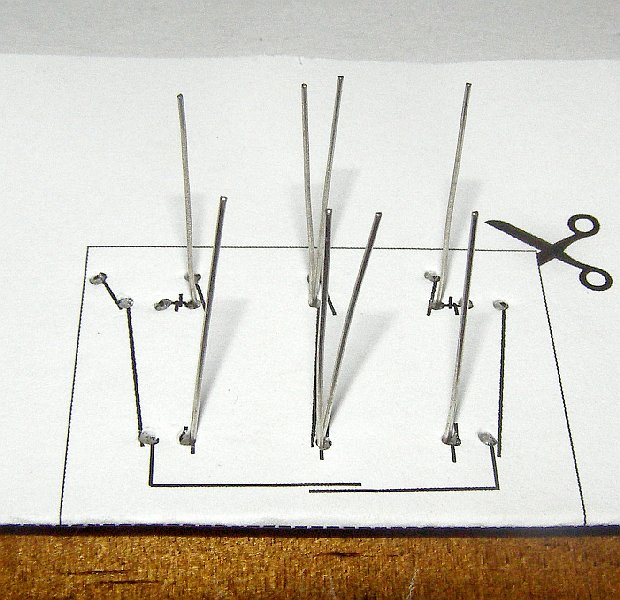
First, we are going to add the 4 resistors to the circuit. Use the long-nose pliers to hold one of the resistor leads close to the body of the resistor and then use your other hand to bend the outside of the lead down at a 90 degree angle. Don't turn the wire using the pliers but hold the wire straight and bend it down with your hand (see the left picture below). This will stop you from damaging the resistors.
Bend the leads on all of the resistors. You can check the spacing by holding them up against the circuit diagram. Carefully slide the circuit part of your cardboard over the edge of the desk or table and insert the resistors into the corresponding holes on the board. The colour bands on the 100Ω resistor are Brown-Black-Brown and the bands on the 20KΩ resistor are Red-Black-Orange. See the diagrams below.
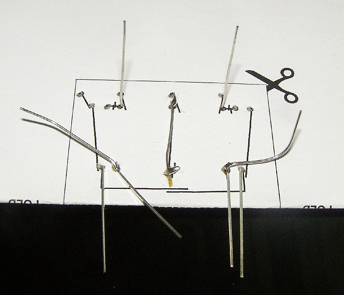
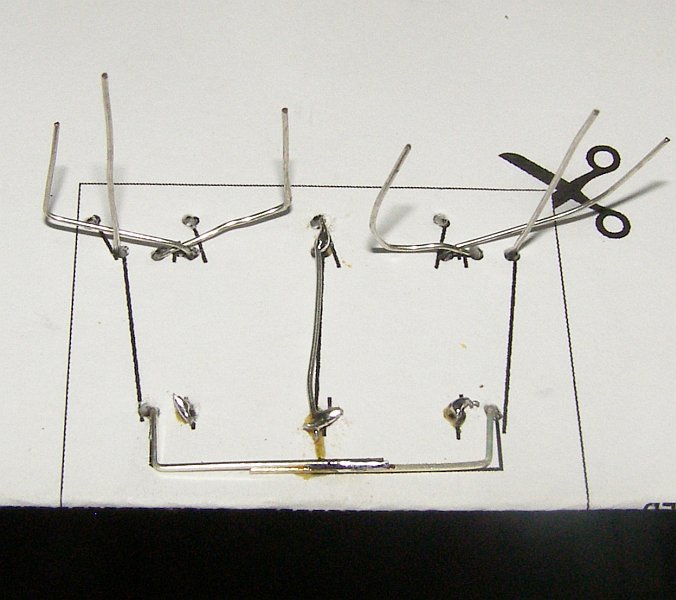
Carefully turn the board over to the "WIRING" side - you could slide a piece of paper over the resistors to help keep them in place while you turn it - and make sure you slide it back over the table so they don't fall onto the floor! It should look like the left image below and there should be two holes in the center that have two wires poking out of them.
A normal Printed Circuit Board (PCB) has copper tracks on it that connect the components and make the circuit but for this board we will use some of the component leads to make the connections instead. Start with the center hole closest to the edge of the cardboard and bend the lead from the resistor on the left side over to the right and the lead from the right resistor over to the left. See the middle diagram below.
Now with the other 2-wire hole bend the leads 90 degrees around each other and lay them flat so that one of the leads runs across towards the edge of the board. Slide this lead under one of the first two wires you bent so that it looks like the picture below. The pictures on the "WIRING" side of the board will help you work out where the leads should go.
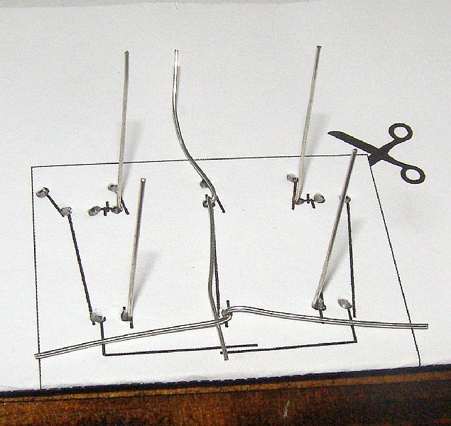
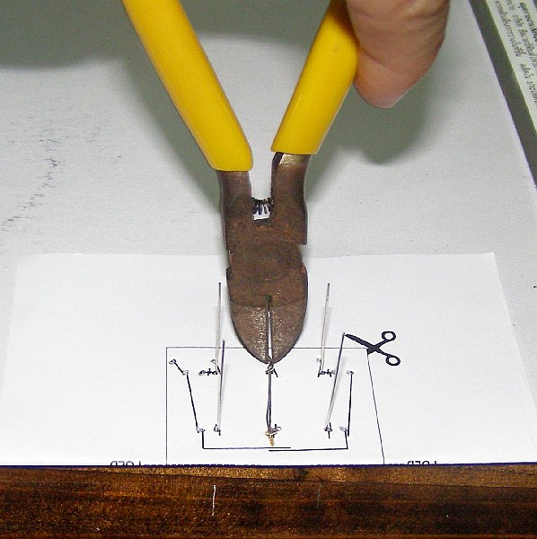
Now you are ready to solder the center wires together (if you haven't soldered before this comic will help you). Solder the 3 wires closest to the edge of the board together then use the side cutters to carefully clip off the excess wire. Do the same for other wires that you bent together so it looks like the picture with the yellow side-cutters above. Make sure that you don't cut the lead that runs across the middle of the board. When you are done it should like the picture on the right above.
![]() Warning! Soldering irons are very
hot. Always be careful when using a soldering iron so that you don't
burn yourself (or others) and never leave an iron that is plugged in
unattended. The fumes from the solder flux or melted plastic can also
be toxic so don't breathe them in and work in a well ventilated area!
Warning! Soldering irons are very
hot. Always be careful when using a soldering iron so that you don't
burn yourself (or others) and never leave an iron that is plugged in
unattended. The fumes from the solder flux or melted plastic can also
be toxic so don't breathe them in and work in a well ventilated area!
| Parts | Tools |
|---|---|
|
|
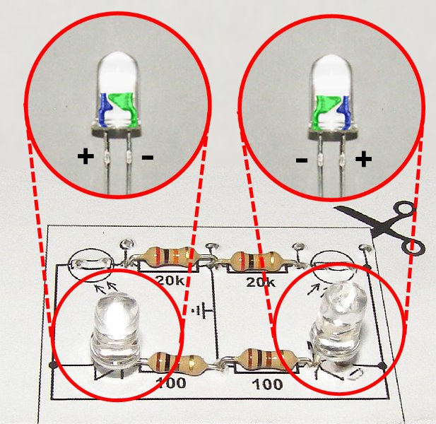
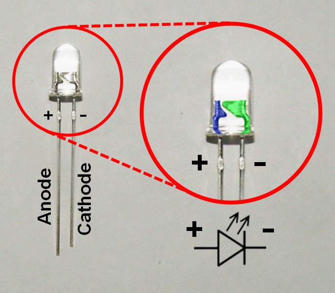 The circuit symbol for an LED is a triangle with an extra line
across one end. The extra line is always on the end that is connected
to the negative or ground side of the circuit. This side of the LED is
called the "cathode" and if you look carefully at an LED you will see
that one lead is shorter than the other. The short lead is the
cathode. The longer lead is called the "anode" and it is always
connected to the positive side of the circuit. If the LED has a clear
case then you can also look inside the LED to work out which side is
the anode and which is the cathode. The anode is thinner (shown in
blue in the close-up on the right) while the cathode is larger and shaped
like an anvil (shown in green).
The circuit symbol for an LED is a triangle with an extra line
across one end. The extra line is always on the end that is connected
to the negative or ground side of the circuit. This side of the LED is
called the "cathode" and if you look carefully at an LED you will see
that one lead is shorter than the other. The short lead is the
cathode. The longer lead is called the "anode" and it is always
connected to the positive side of the circuit. If the LED has a clear
case then you can also look inside the LED to work out which side is
the anode and which is the cathode. The anode is thinner (shown in
blue in the close-up on the right) while the cathode is larger and shaped
like an anvil (shown in green).
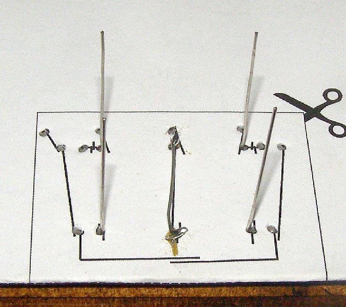
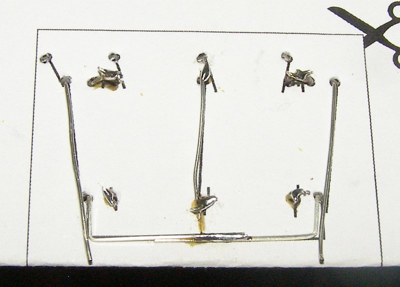
Turn your board back over to the "CIRCUIT" side and position it over the edge of the table again. Insert both of the LEDs so that the short leads share a hole with the 100Ω resistors. You will notice that there is a wider part on each of the LEDs' leads. Remove one of the LEDs from the board and use the long nose pliers to hold both leads just below the wide part. Use your other hand to bend both of the leads at 90 degrees so that when you return it the board the leads will point out away from the table and the edge of the board (see the first two images below). Do the same with the other resistor and check to make sure that the shorter cathode leads are still closest to the resistors or have a look at the 'anvils' inside the LED (as in the third image below).
When you mount the LEDs make sure that the bottom of the LED is not flush with the board - there should be a 5mm gap between the bottom of the LED and the board (see the second picture below). Later on in Step 15 you may need to adjust the angle of the LEDs. Bending the legs of the LEDs as described above will leave enough room so that you will be able to adjust them later.
Turn the board over and bend the remaining 100Ω resistor leads outwards (see the picture above right) then solder the cathode and resistor leads together. Clip off the excess wire from these two leads but make sure that you don't clip the anodes.
Use the long-nose pliers to hold part of the anode lead as shown in the image below left and then bend the rest of the lead at 90 degrees so that it matches the wiring diagram printed on the board. Do the same for the other anode so that the ends of the wires are side-by-side. Solder the two anodes together so it looks like the middle image below and then turn the board back over to the "CIRCUIT" side. Your circuit board should now look like the image below right.
| Parts | Tools |
|---|---|
|
|
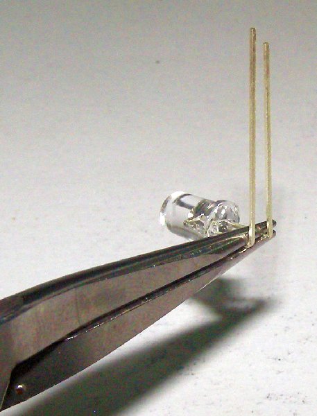
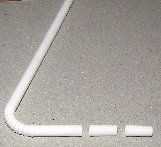
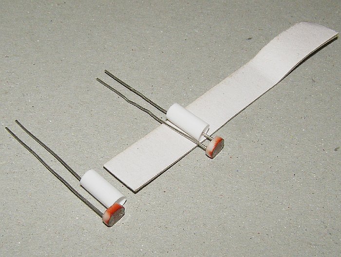
Cut a 1cm x 6cm strip of cardboard and also cut two 1cm long pieces off the end of the plastic juice-box straw. If you can't find a juice-box straw then you could substitute two 1cm lengths of Chupa Chup stick, ballpoint pen ink-casing, or small rolled paper tube. Slide a length of straw over one leg of each LDR. See the first two images below.
Next, insert the LDR leads into the circuit board and thread the piece of cardboard between the leads as shown in the picture below. Hold onto the LDRs and carefully turn the board over to the "WIRING" side. Make sure that the LEDs and LDRs are hanging over the edge of the table (but don't let the LDRs fall out!).
Bend the two inner LDR leads in towards the 20k resistors and bend the remaining 20k resistor leads outwards so they overlap as shown in the first image below. Solder the overlapping resistor and LDR leads together and clip off the excess wire.
Next, bend the remaining LDR leads down alongside the LEDs as shown by the wiring guide printed on the board (see the middle image below). Solder the leads together and clip off any excess wire that sticks out past the 90 degree LED leads. If you turn the board over it should now look the image below right.
| Parts | Tools |
|---|---|
|
|
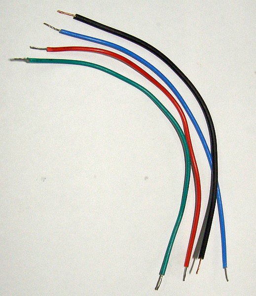
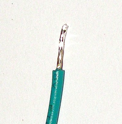
Cut four pieces of hookup wire 12cm in length. Ideally one red for the +5V connection, one black for the ground connection (GND), and two of different colours for the joystick axes (green and blue in this example). Use the side cutters and the soldering iron to strip and tin 1cm sections on the ends of the wires so they look like the images below.
Next use the long-nose pliers to put a 90 degree bend in one end of each wire. Poke the bent end of the wire through the holes from the circuit side of the board and solder them to the nearest existing wires on the wiring side. As before you can use the diagram printed on the wiring side of the board as a guide. Connect the red wire to 5V, black to GND, and the other two wires to the joystick axes.
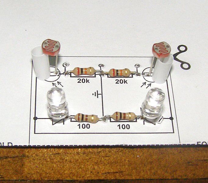
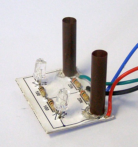
From the circuit side your board should look like the figure below left. NOW YOU CAN CUT AROUND THE CIRCUIT but be very careful not to damage the wires you just connected. The last you thing you need to add to the sensor are some shields for the LDRs so that the only light they "see" comes from the floor beneath the robot. Cut two 2.5cm lengths from a brown or black drinking straw. Slide these over the LDRs (the smaller juice-box-straw sections should fit inside OK) and then use some hot-melt glue to keep them in place as shown below. The line detector is now ready to be connected to the joystick and then mounted underneath the robot.
![]() Warning! Hot-melt glue is very hot
(hence the name). It will stick to your skin and can cause serious
burns so be careful! Don't leave the glue gun unattended and make sure
you unplug it when you are finished.
Warning! Hot-melt glue is very hot
(hence the name). It will stick to your skin and can cause serious
burns so be careful! Don't leave the glue gun unattended and make sure
you unplug it when you are finished.
For this step you will need these parts & tools:
| Parts | Tools |
|---|---|
|
|
The brown component side of the thumbstick board contains two mini joysticks and looks the same in any Dualshock-like joystick. However, the layout of the circuit on the bottom of the board will vary from manufacturer to manufacturer. In this step we will look at the circuit to work out where to connect the four wires on the line sensor you made in the previous steps.
If the thumbstick board in your joystick looks one of the two below (from an 'OKER' brand clear-bodied joystick) with 'M-918B' or 'VNS706-3D REV1.0' printed on the board then you can click on the corresponding images below for a board specific version of this step.
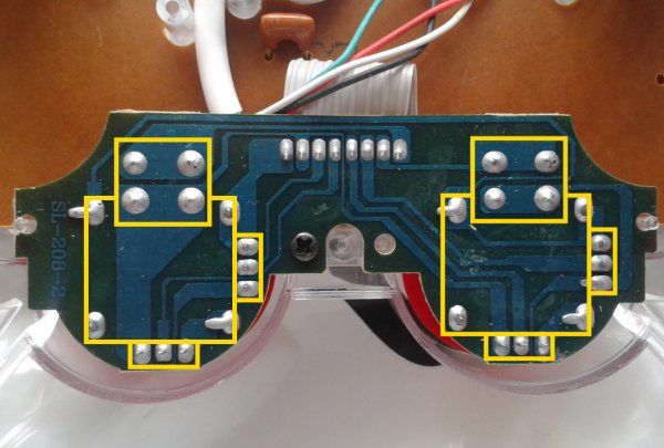
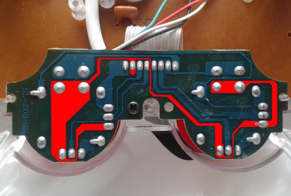
In the first image below I have overlaid the position of the two mini joysticks on the other side of the board in yellow. The small squares towards the top of the image are the buttons (you can click down on the thumbsticks) while the larger square shape is the body of the joystick. This is the bottom of the board so the sides are reversed - the right-side thumbstick is the one on the left and the left stick is the one overlaid on the right. The rectangles on the side of the mini-joysticks with three solder connections are the Y-axis variable resistors and the ones along the bottom are the X-axis resistors.
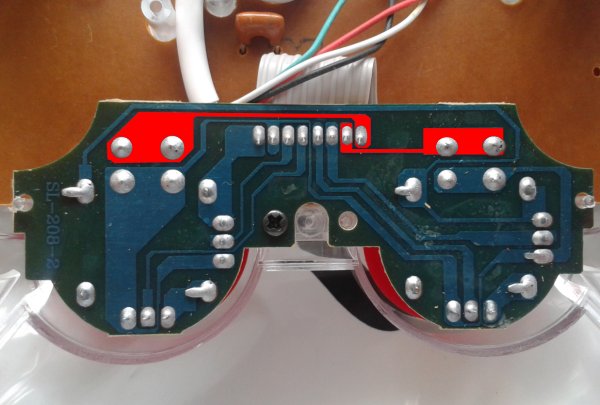
The ribbon cable that connects this board has eight wires: 2 for the buttons, 4 for the joystick axes (X and Y for each joystick), +5V, and ground. The 2 button wires are the easiest to identify and the wiring for these will simply run from one side of the cable connection to each of the buttons. They wiring won't be connected to any other components - just the buttons. See the right image below which has the button traces overlaid in red. If we number the cable wires from left to right then the "left" button will be wire 7 and the "right" button wire 8.
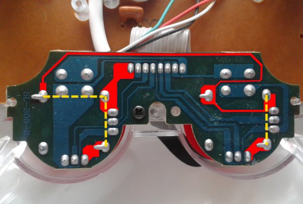
The wires for the joystick axes are also easy to identify because they are connected to the center pin of the joystick resistors. You can follow the wiring back from each of the resistors to the cable connection as shown in the image below left. On this board wires 3 and 4 are the Y-axis and X-axis for the right joystick and wires 5 and 6 are the Y-axis and X-axis for the left joystick respectively. So far you have identified 6 of the 8 wires - only two to go!
All of the components on this board (the four joystick variable resistors and the two buttons) share one common connection and on USB joysticks this is normally connected to the +5V wire. An easy way to find this is to find a connection between one of the buttons and one of the variable resistors and follow it back to the cable connection. The +5V wiring is shown in red in the image below right.
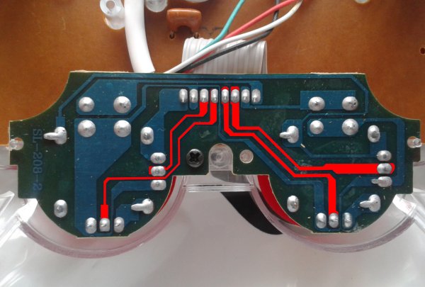
By a process of elimination that means wire 1 must be the ground connection! This is easy to check because the ground connection is only connected to the variable resistors (and NOT the buttons). See the first image below. The only trick here is that sometimes the circuit designers use the metal body of the mini-joystick as a wire to connect parts of the circuit (overlaid in yellow). So while it looks like there are 4 separate red sections in this image they are all actually connected back to pin one.
By just looking at the board you have been able to work out what the connections are but if you have a multimeter you can plug the joystick in carefully and check your +5V and ground wires. Choose a DC Voltage setting that is greater than 5V and connect the black lead to wire 1 (ground for this particular joystick board) and the red lead to wire 2 (+5V). Make sure you don't touch the leads together. If it doesn't read as around +5V then go back over the circuit again.
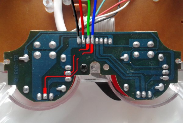
Now that you know which wires are which you can connect the line sensor. Use the side cutters to clip the ends of the wires down to around 4mm in length and then solder the sensor's:
See the middle picture below.
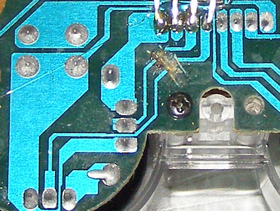
You now need to disconnect the joytick's resistors so that they don't interfere with the voltage dividers in the line detector. If you look carefully in the image below you will see that part of the right joystick wiring has been removed. Use the craft knife to carefully make two cuts about 2 or 3mm apart in the wiring to the X and Y joystick axes - you may need to choose a different location on your joystick. Heat the section in-between the cuts with a soldering iron for about 10 seconds and then you should be able to carefully remove it from the boards using the craft knife (see the image below right). If you have a multimeter you can check that this part of the circuit is now open so there is no connection between the joystick's resistors and your joystick axis wires.
Note that the picture of the thumbstick board that I've used in this step is still screwed into the joystick but yours will still be loose - for now.
For this step you will need these parts & tools:
| Parts | Tools |
|---|---|
|
|
Now it's time to re-assemble the joystick but first you need to make a small hole in the lower half of the joystick case/shell near the USB cable for the line sensor wires (see the image below left). You could carefully melt a hole in from the edge using the soldering iron (beware of the smoke!) or wrap the sandpaper around a pen or pencil and file a small opening. It only needs to be big enough for the 4 wires to fit through with the case closed.
Next you will need to re-attach the rumble motor leads to the circuit board. Refer back to the notes you made about their rotation in Step 1 and any photos you took in Step 3. If the motor was already turning in the right direction then reconnect the wires in the same positions as they were in back in Step 3. Otherwise you can just swap the positions of the two wires to reverse the motor's direction.
Now you can re-fit the buttons and circuit boards back into the joystick. Refer back to any photos you took during Step 1 that may be helpful. Some joysticks also include a plastic support as part of the D-pad which looks like the middle image below in case you were wondering where it went. Don't forget to re-fit the thumbsticks and screw the thumbstick board back into place.
Position the motors carefully in the holes you made and close the case (make sure the motor shafts are perpendicular to the cut-sides of the joystick as in the left image below). Keeping all of the buttons and the motors in place can be a little tricky but be patient and you can do it. Hold the joystick together with one hand (or get a friend to help you) and re-place the rest of the screws. Be careful not to over tighten them.
Before continuing you should check that your motors turn in the right direction. The left-side motor should rotate in an anti-clockwise direction (see the middle picture below) while the right-side motor should rotate in a clockwise direction (right picture below). If one of the motors is rotating in the wrong direction then re-open the joystick, swap the two wires, and then carefully close the case again.
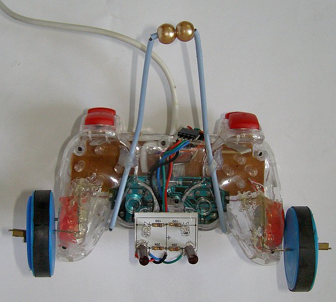
Now you can flip the joystick over and attach the line sensor underneath the robot using hot-melt glue. Position the board carefully so that the LDRs are underneath the thumbsticks and as far forwards as possible so that the screw hole is still accessible (see the picture below left). Mounting the line sensors as far forward as possible makes it easier for Lollybot to follow a line. You can carefully bend the wires in so they run between the board and the bottom side of the joystick. Glue the board in place and then turn the joystick over and add a little more hot-melt glue between the wires side of the board and the bottom of the thumbstick wells (see the picture on the right below). The straw shields are easily damaged so put the joystick down on its back somewhere safe. Now it's time to make the wheels.
For this step you will need these parts & tools:
| Parts | Tools |
|---|---|
|
|
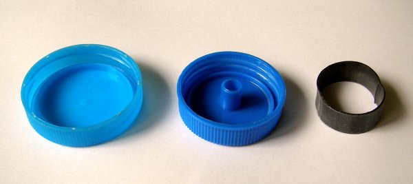
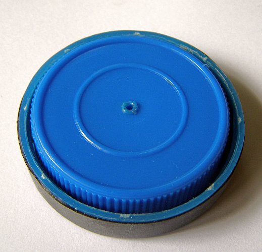
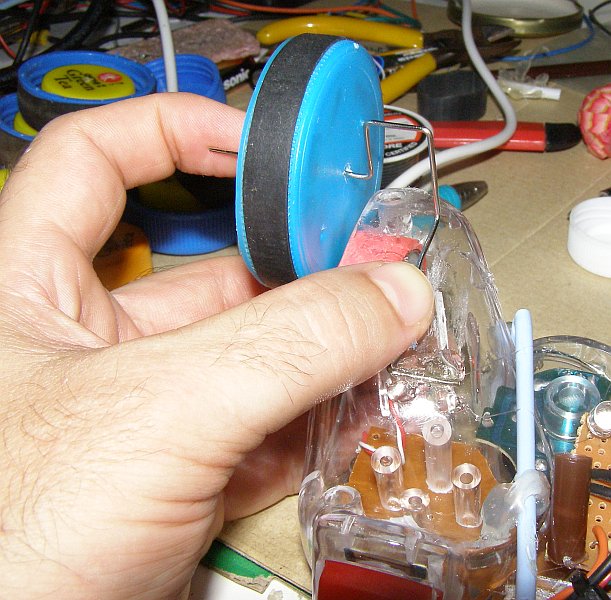
In this step you will make Lollybot's wheels. Start by using the scissors to cut two 1cm wide sections of rubber from the old inner tube and turn them inside out. Next take the lids that you will use for the wheels. The lid for the outer wheel should be at least 45mm in diameter while the lid for the inner hub should fit neatly inside of the outer wheel (see the middle diagram below).
Before you glue the wheels together you want to melt a small hole (just big enough for the paperclip wire to pass through easily) in the center of each of them using the soldering iron (clean the tip of the iron afterwards). Some lids have injection moulding marks on the inside that may help you to find the center but try to be as accurate as possible because this can affect your wheels performance. Once you have melted the holes put some hot-glue between the lids and glue them together. Stretch the rubber tube section over the outer wheel and it should look like the image below right.
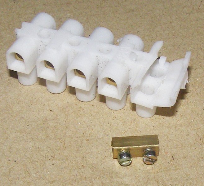
The wheels will be held in place on the axles by two small screw terminals which must be cut from the terminal block. Use the utility knife to carefully cut through the plastic on the bottom of the screw terminal block and then bend it open. You should be able to slide the screw terminal straight out.
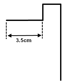
Start making the axles by straightening the two paperclips (use the pliers) and then measure 3.5cm in from one end and make a 90 degree bend. Then add a bump the height and width of the jaws of your pliers (simply hold the wire next to the last 90 degree bend and bend again) so it looks like the middle image below. The next two bends will be made when you mount the wheels in the next step.
![]() Warning! Soldering irons, hot-melt
glue guns and hot-melt glue are very hot and could burn you badly.
Always be careful when using them and never leave an iron or glue
gun that is plugged in unattended. The fumes from the solder flux or
melted plastic can also be toxic so don't breathe them in and work in
a well ventilated area!
Warning! Soldering irons, hot-melt
glue guns and hot-melt glue are very hot and could burn you badly.
Always be careful when using them and never leave an iron or glue
gun that is plugged in unattended. The fumes from the solder flux or
melted plastic can also be toxic so don't breathe them in and work in
a well ventilated area!
For this step you will need these parts & tools:
| Parts | Tools |
|---|---|
|
|
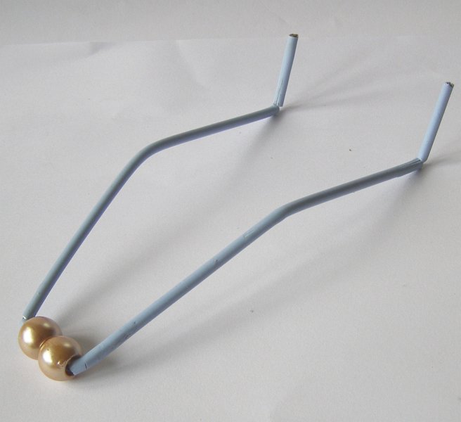
Use the side of the pliers to make a cut in the coathanger close to the hook and then straighten it. Now cut a 33cm length of wire from your straightened wire and start on one end by measuring in 3cm and making a 90 degree bend with the pliers. Refer to the image below. Measure 6cm and make an approximately 10 degree bend. Measure another 6cm and then make a 100 degree bend that will be at right angles to the first 3cm section. This will be the part that holds the beads.
Before you thread the beads measure along 2.5cm and start to mirror the bends you have already made BUT thread the beads onto the wire before you complete this bend. Once you have finished bending the skid turn the joystick over and lay the skid beneath the joystick so the two 3cm upright sections are next to the thumbstick wells and the beads are towards the USB cable-end. Make sure that wire passes on either side of the line-sensors straws and be careful not to damage them. Make any minor adjustments you need to get the bends so that it fits nicely beneath the joystick.
The skid is held in place with hot-melt glue - along the front by the thumbstick wells (see the middle image below) and then underneath the joystick close to the LDR tubes (see the last image below). Glue the skid into place.
You can now finish bending the axles and mount Lollybot's wheels. Slide one of the wheels onto the first 3.5cm wheel section that you bent and hold it against the side of the joystick and on top of the motor shaft (see the first picture below). You want to make an approximately 120 degree bend back long the body of the joystick so the section closest to the wheel remains upright. Bend the wire along the bottom of the joystick for about 3.5cm so it matches the curved shape. Bend the remaining section of the paperclip at 90 degrees in towards the line-sensor.
When you are working with the paperclips try not to rebend them too much or you might introduce a weak point. If this happens and your suspension breaks you can carefully peel off the hot-melt glue using the end of a knife (be very careful or something like a small flat-blade screwdriver and make a new axle.
Hold the wire in place and carefully add some hot-melt glue to the last right angle bend you added and keep holding until the glue starts to harden. You can now slide off the wheel and add some more glue towards the wheel end as in the middle picture below. Once that glue starts to harden you can cover the rest of the paperclip along the bottom of the handle in glue. Wait a few minutes and then slide the wheel on and secure it in place with a screw terminal. Repeat the process for the other wheel. You will adjust the wheels in the next and final step.
For this step you will need these parts & tools:
| Parts | Tools |
|---|---|
|
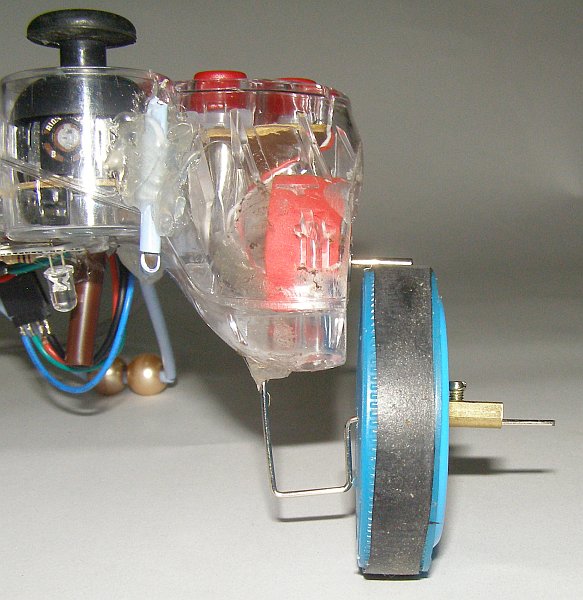
|
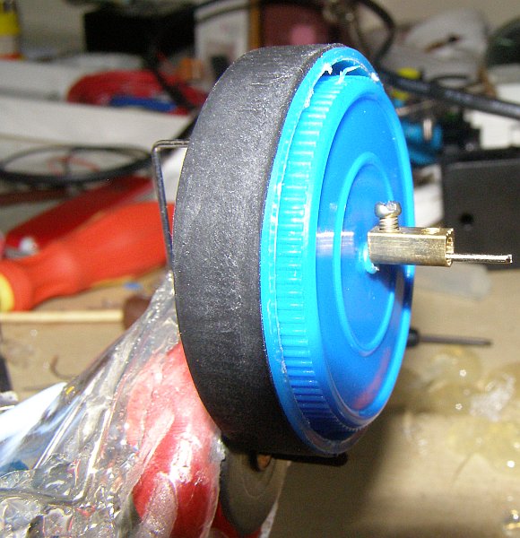
Below is a picture of my Lollybot without the wheels. The axles can be bent to adjust the position of the wheels relative to the motor shaft. This takes some trial and error but provided your wheels are reasonably centered you should be able to adjust them so they work well - be patient. Start by loosening the screw terminals with the flat-blade screwdriver and bending the axles so that the tires are pushed against the shaft and the wire next to the ties lines up well with the side of the joystick (see the middle picture below). Re-fit the wheels and then bend them down so that the axle is only pushing the wheel lightly against the shaft. When you run Lollybot's software in drive mode (press the 'A', 'W', and 'D' keys to drive) you will be able to hear when the motor shafts are slipping (and Lollybot won't move). Check that the axles are not pushing too loosely or too tightly on the motor shaft.
You also want to try and position the wheel so the motor shaft is trying to "climb" onto it as it turns. See the last picture of the wheels from the side below. You should also try and make sure that the axles are parallel to the motor shafts. It may take a little trial and error but you should be able to get your wheels working reliably.
You are now going to adjust the line sensor. See the two images below for views from the front and side of the sensor beneath Lollybot. Essentially the Straw sections with the LDRs inside should be looking at the light from LEDs. Run Lollybot's software, choose the joystick that corresponds to your robot and then press the "analog" button on the joystick. You should now be able to see the values being read from the line sensors displayed as red and blue lines on the graph. If you don't see them changing try selecting a different axis using the "Choose axis" combo boxes. These steps assume that you are leaving the left joystick as the bump sensor and connecting the right joystick to the light sensors.
Place a piece of white paper underneath Lollybot and if the sensor's are reading different values you should try adjusting the one with the lowest line until they are similar (they don't have to be exactly the same to work). You should be able to adjust the angle of the LEDs so that the light is projected directly beneath each of the straws.
You should now have a working Lollybot. If your robot doesn't
work try re-checking the steps to make sure that you followed them all
carefully. Make sure you clean the wheels regularly - this will cause
them to slip and try to avoid dusty floors as this will make the
wheels dirty very quickly. You should also untangle Lollybot's USB
cable regularly while it is being used. It is a tethered robot and
twisting the cable too much will eventually cause the wires inside to
break and your robot will stop working. Good luck!
This section of the submission is included for robots that might cost more than $10 but whose cost could be reduced if they were manufactured in larger quantities. Lollybot costs less than $10 and is designed to be built by the user so this section does not apply.
With the control and telemetry software for Lollybot you can check all of the robot's sensors, drive your robot using the keyboard, and try out the bump mode. Two versions of the software are available:
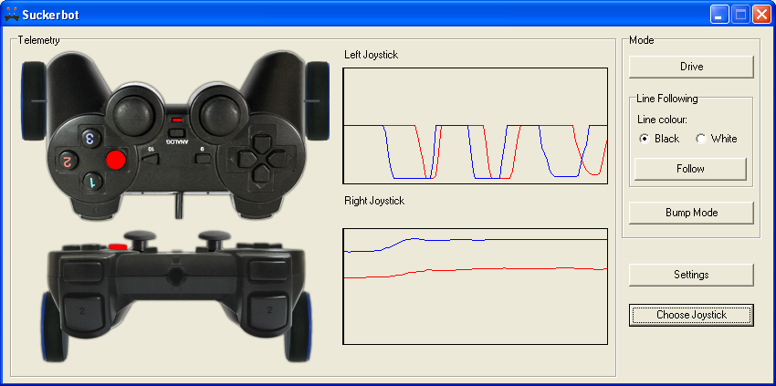
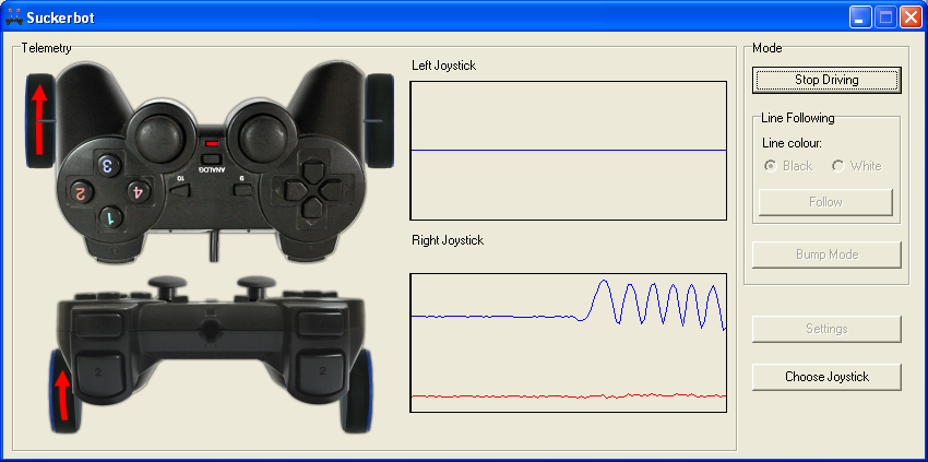
The original version of Lollybot's control software was written using Delphi 7 for Windows and is released under the GNU GPL v2 license. Here is a screenshot of the main interface with the robot telemetry:
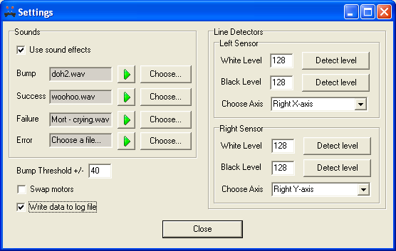
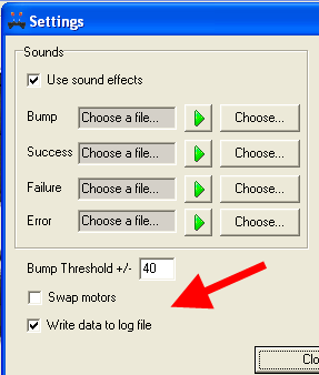
Below is a screenshot of the settings screen. All of the options are now implemented. From this screen you can also set some amusing sound effects, adjust the bump threshold, swap the motors, choose which joystick axes are used for the line detectors, and turn logging on/off.
The white and black levels for the line sensors can be entered manually or you can press 'Detect Level' to set them from the values currently coming fom the sensor. If you place Lollybot over a black line, for example, you can then press the 'Detect Level' buttons to set the black levels. Move Lollybot so it is off the line and you can do the same to set the white levels.
You can download the source and a binary distribution for Windows 32-bit operating systems here:
Both the source and the executable are available from Suckerbot's GitHub project page. If you are going to build the software from the source you will also need the HID USB class and demo's for Delphi:
HIDKomponente.zip (372 KB)
HTML5 + JavaScript version
This cross-platform version of Lollybot's telemetry and control software is implemented in HTML5 and JavaScript. It uses Node.js and the interface is designed to run in any modern HTML5 compliant web-browser. Here is a screenshot of the interface running in Chrome on Windows:
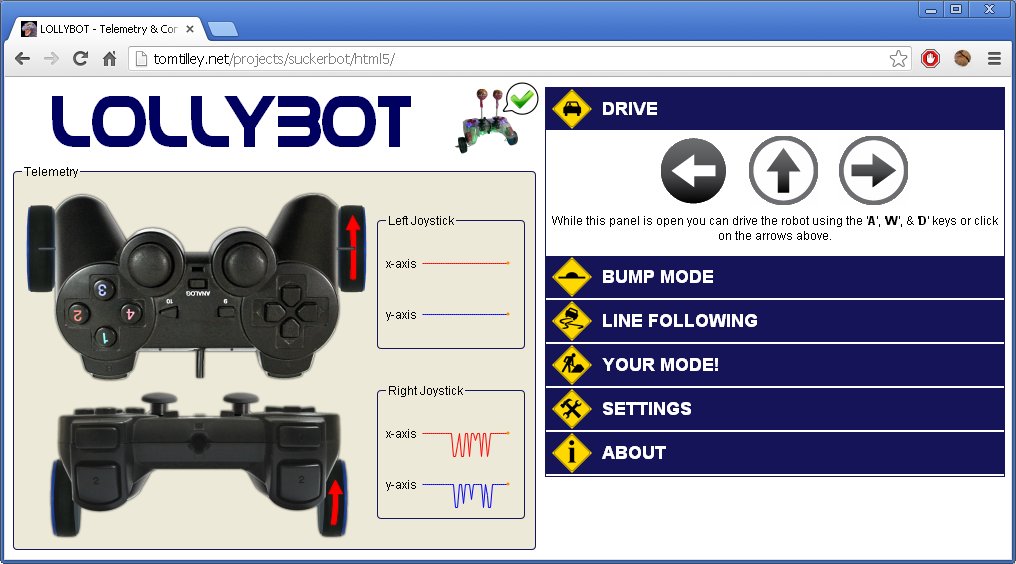
The software is released under the GNU General Public License v3.0 and you can download the latest version here.
You can also find out more on the Lollybot GitHub project page, including an overview of how it works and some help for writing your own control mode.
You can see what the interface looks like (or connect to a robot attached to a server) by visiting a live version of the HTML5 page.
These are some of the experiments I conducted during Lollybot's development.
Wheels
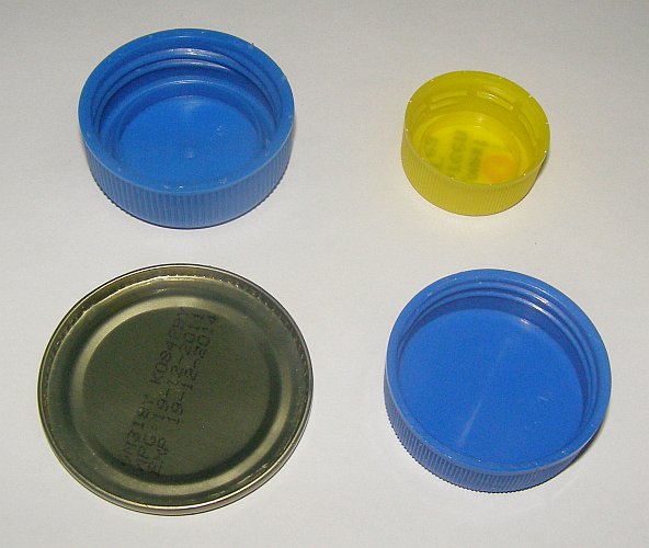
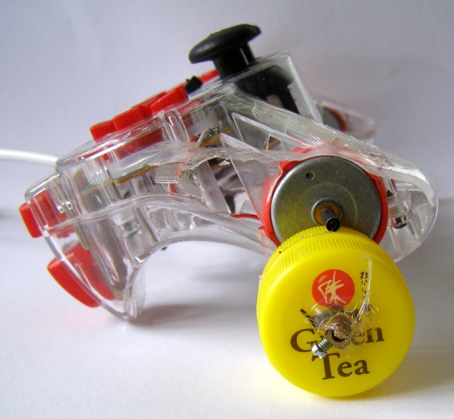
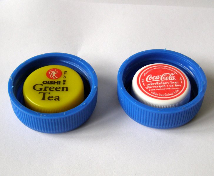
After I had modified my first joystick to rotate the position of the rumble motors and expose the motor shafts I needed to find some wheels for Lollybot. I started by scavenging a range of lids from things like canned fish, and various water, milk, green-tea, and soda bottles. My initial idea was to mount the wheels directly on the rumble motor shafts - both of which conveniently rotated in the right directions so that the wheels would pull the joystick along with the cable trailing along behind. Given the position of the rumble motor shaft I chose some milk bottle lids to try as wheels because their diameter was just large enough to lift the joystick handgrips off the ground.
I carefully melted a hole in the center of the wheel using a soldering iron and inserted the metal sleeve from one section of a screw terminal block. The screws would allow me to secure the wheel to the shaft. I also melted a small hole in the rim of the wheel so I could access and tighten the screw "inside" the wheel.
The first control mode that I implemented in Lollybot's software was the driving mode specifically so I could test the wheels. Unfortunately, my first test drive was less than successful because the motors were not strong enough to turn the wheels (the USB standard only supplies 5 Volts). I tried experimenting with successively smaller wheels - down from milk bottle lids to soda bottles and then to some white plastic screw posts cut from the back of an old fan (see the image below, right) hoping that the joystick may be able to pull itself along like Mousey the Junkbot.
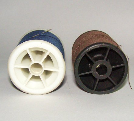
After these failed attempts I came to realise that some form of gearing mechanism was going to be required which would reduce the speed of the wheels but increase the torque. Using gears would require scavenging parts from equipment like old CD-ROM drives and I didn't think these would be readily available for most students. It also meant a required degree of precision during assembly that may be hard to achieve and replicate with simple tools. So I decided to try an experiment using some cotton reels mounted on a chopstick shaft driven from the motor using rubber bands.
Getting the amount of tension right and keeping the bands in place was difficult so I searched for an alternative design but it gave me hope that a simple gearing mechanism may work. I glued two soda bottle lids together using hot-melt glue and mounted them on an axle made from a wooden skewer. A section of juice-box straw glued underneath the robot acted as a sleeve for the axle and this was secured in place with a screw terminal. The wheel was driven directly off of the plastic screw post and if I assisted the robot by holding the cable to lift the rear part off the ground it was able to move - albeit somewhat unreliably - for the first time. Using this approach to drive the wheels meant that the wheels pushed the robot in the direction of the USB cable and so I had to open the joystick and resolder the motor wires to reverse their polarity.
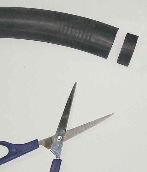
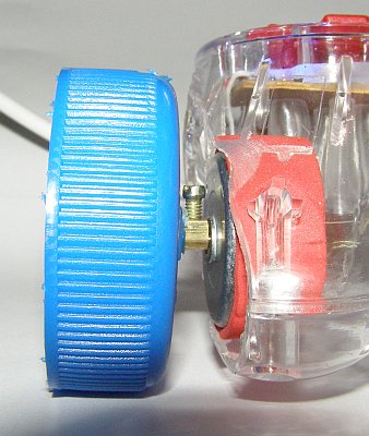
To further increase the torque I removed the screw post so that the shaft of the motor itself was in contact with the wheel. To help stop it from slipping I shrunk a piece of heat-shrink tubing directly on to the shaft (see the image below, right).
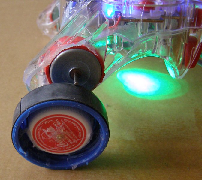
By further increasing the diameter of the wheels (back to milk bottle lids) I had my first set of reliable wheels that provided enough torque to pull the robot (and the USB cable) along. 45mm appears to be about the minimum useable wheel diameter. To help keep the axle straight I used a soda bottle lid as a hub which was glued inside the larger wheel. It was very difficult, however, to mount the axles so that they were perfectly centered and any wheel imperfections resulted in unreliable wheels.
Stretching a piece of rubber cut from a bicycle tire inner tube helped to increase the grip on the wheels so that the heat-shrink tubing was no longer required on the motor shaft but getting the axles and sleeves to work reliably required a lot of adjustment. I decided that I should try and find a more "forgiving" way of mounting the wheels.
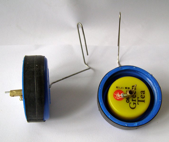
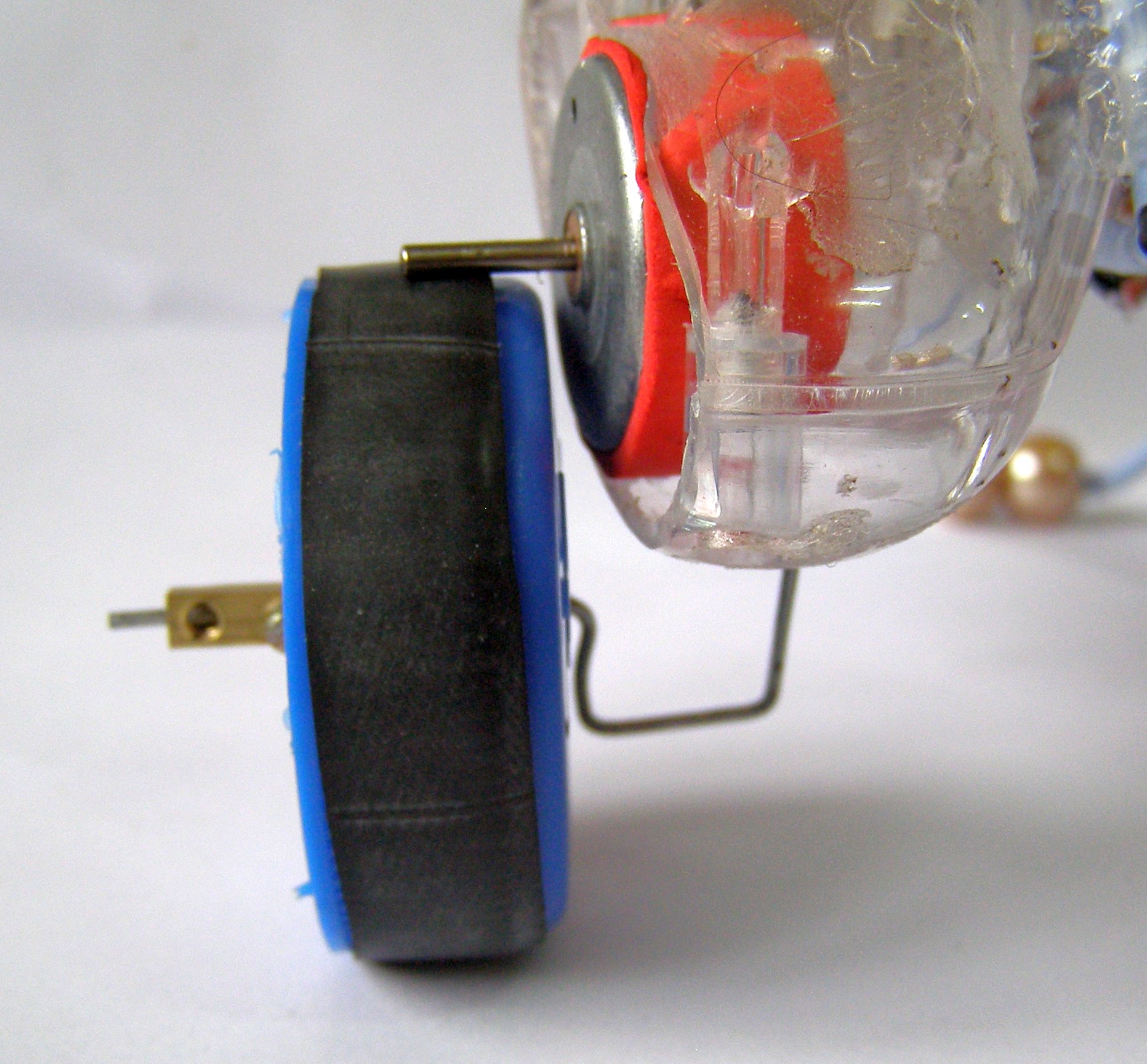
Using some large paper clips I fashioned some simple axles that were hot-melt glued underneath the robot. They were rigid but still flexible enough that they would bend slightly under the weight of the robot to provide contact with the drive motor. The wheels simply had two small holes melted into either side to allow the axle to pass through and a screw terminal holds the wheel in place. A square "U"-shaped bend in the paper clip stops the wheels from bending in beneath the robot.
This design is quite forgiving of wheels with axle holes that are slightly off-center and although the axles require some initial adjustment they can be easily bent into a position where they work reliably. The wheels shown below appear in the "initial wheel test" part of the video. The current version of Lollybot uses this same design but with 51mm wheels made from 6 litre water bottle lids.
As discussed in Section 1 the variable resistors in the analog thumbsticks act as voltage dividers that vary the USB supplied 5V between 0 and 5 Volts. I built a quick prototype circuit using some breadboard and a re-bodied USB joystick (the black box with the blue DB-25 connector at the top of the left image) that only required 4 components, an LED, an LDR and two resistors.
Although LDRs respond best to green light with a wavelength of about 520nm my test circuit worked well with a bright blue LED that I had on hand. I chose a 20KΩ resistor to use as the "lower half" of the voltage divider and this provided a good variation in voltage levels when tested with a hand-drawn black line on white paper. I then constructed a two-sensor circuit on wire-wrap board (but soldered the connections rather than actually wire-wrapping them). This was the board I used to test the robot while experimenting with the line following code and I planned to use this approach for building the line detector in the final design. However, while thinking about ways to reduce the cost of the robot I found a forum thread on making circuits using cardboard.

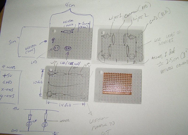
A cardboard "PCB" would literally be a very cheap printed circuit
board with the circuit diagram on one side that the students could
overlay with the actual components as they added them to the circuit
and a wiring guide on the other. After a number of layout iterations
I came up with this circuit
template. During construction of the printed board I realised
that it would make more sense for the two sides of the template to be
mirrored so that the hook-up wires are on the "fold" edge of the board
- but I had already taken photographs for the instructions
in Section 6 and the challenge deadline is
looming!
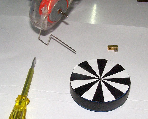
Wheel Patterns
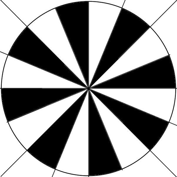
Lollybot uses the DC joystick motors to drive the wheels and these are obviously less accurate (and less powerful) than stepper motors. The simple drive mechanism on Lollybot also means that it is possible for wheels to slip and the combination of different motor strength and manufacturing differences means that there can be performance differences between the wheels. In this experiment I made a simple pattern with sixteen alternating black and white sectors which I printed and glued to one of the wheels (see the first image below).
I glued my line detector circuit temporarily to the front of the robot so that one of the line detectors could "see" the wheel pattern (see the second image below). As the wheel rotates the sensor observes the changing pattern and this can be seen on the right-joystick graph in the screen capture of Lollybot's telemetry below (third image). The software also has an option to write all of the telemetry data to a log file for debugging/analysis.
The diameter of the wheels is 51mm so the distance travelled during
a single rotation is PI * 51mm = 160mm. There are 8 black and 8 white
sectors on the wheel that correspond respectively to troughs and peaks
on the graph. The distance between these peaks then is 160mm/8 =
20mm. This technique could be used to improve Lollybot's "accuracy"
so that it could be given commands to travel or turn a set distance -
perhaps for simple navigation or drawing tasks. This would help
compensate for slipping within the wheel mechanism and it may be
possible to use smaller sectors.
This video shows the current state of Lollybot's development:
You may also be interested in reading about some of my other projects: